Note
Hello, welcome to the SunFounder Raspberry Pi & Arduino & ESP32 Enthusiasts Community on Facebook! Dive deeper into Raspberry Pi, Arduino, and ESP32 with fellow enthusiasts.
Why Join?
Expert Support: Solve post-sale issues and technical challenges with help from our community and team.
Learn & Share: Exchange tips and tutorials to enhance your skills.
Exclusive Previews: Get early access to new product announcements and sneak peeks.
Special Discounts: Enjoy exclusive discounts on our newest products.
Festive Promotions and Giveaways: Take part in giveaways and holiday promotions.
👉 Ready to explore and create with us? Click [here] and join today!
Lesson 6 Relay
Introduction
As we may know, relay is a device which is used to provide connection between two or more points or devices in response to the input signal applied. In other words, relays provide isolation between the controller and the device as devices may work on AC as well as on DC. However, they receive signals from a micro-controller which works on DC hence requiring a relay to bridge the gap. Relay is extremely useful when you need to control a large amount of current or voltage with small electrical signal.
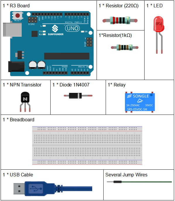
Components
Schematic Diagram
Connect a 1K resistor (for current limiting when the transistor is energized) to pin 8 of the SunFounder Uno board, then to an NPN transistor whose collector is connected to the coil of a relay and emitter to GND; connect the normally open contact of the relay to an LED and then GND. Therefore, when a High level signal is given to pin 8, the transistor is energized, thus making the coil of the relay conductive. Then its normally open contact is closed, and the LED will light up. When pin 8 is given a Low level, the LED will stay dim.
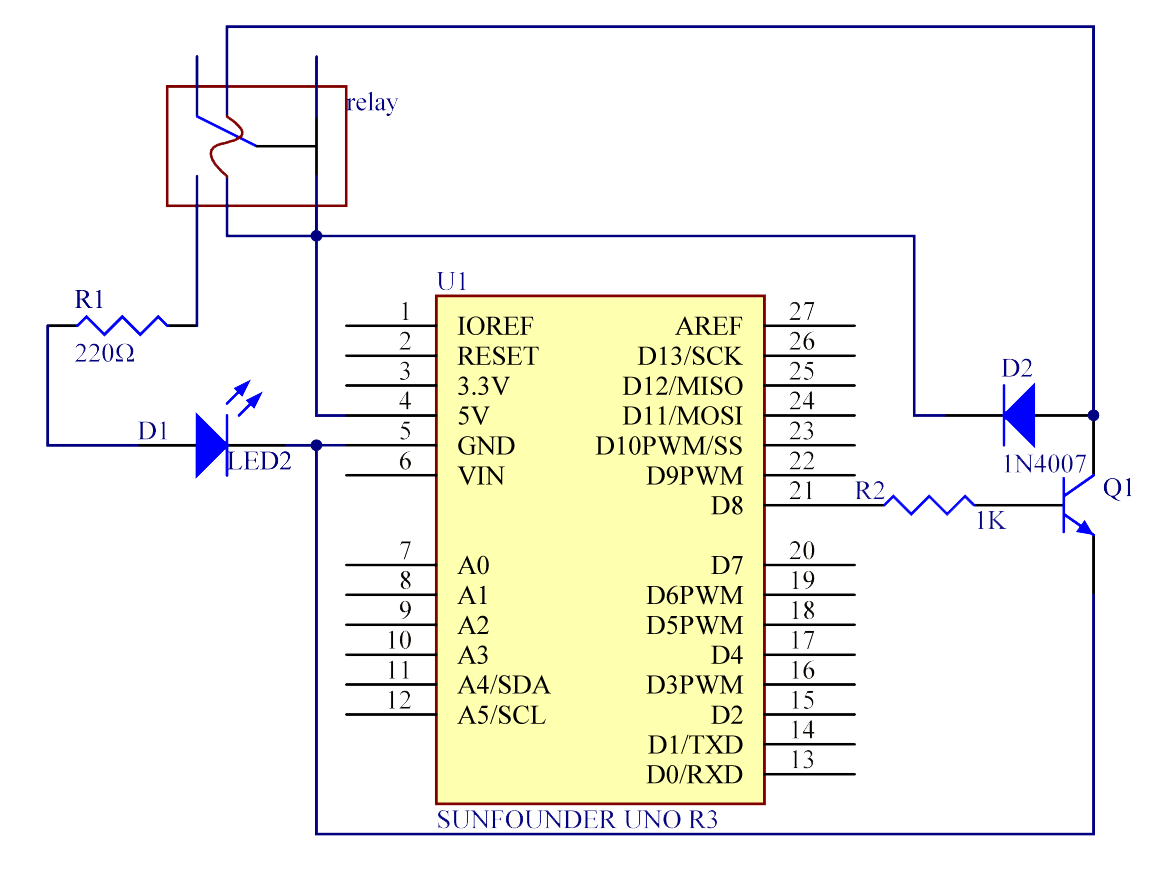
Function of the freewheeling diode: When the voltage input changes from High (5V) to Low (0V), the transistor changes from saturation (three working conditions: amplification, saturation, and cut-off) to cut-off, the current in the coil suddenly has no way to flow through. At this moment, without the freewheeling diode, a counter-electromotive force (EMF) will be generated at the ends of the coil, with positive at the bottom and negative at the top, a voltage higher than 100V. This voltage plus that from the power at the transistor are big enough to burn it. Therefore, the freewheeling diode is extremely important in discharging this counter-EMF in the direction of the arrow in the figure above, so the voltage of the transistor to GND is no higher than +5V (+0.7V).
In this experiment, when the relay closes, the LED will light up; when the relay opens, the LED will go out.
Experimental Procedures
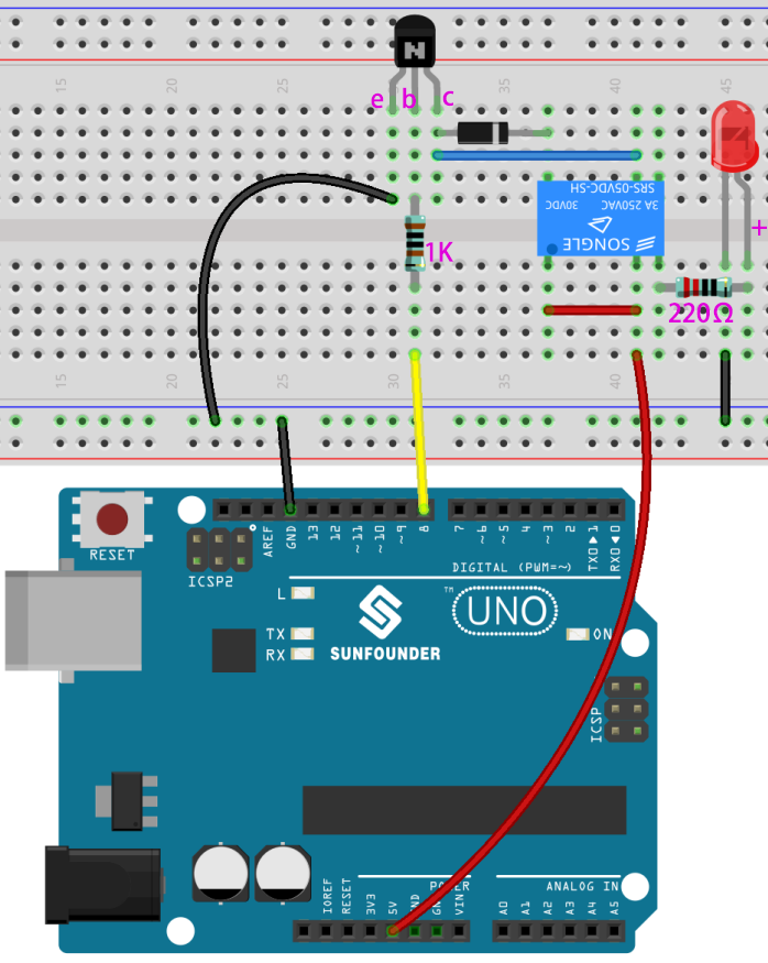
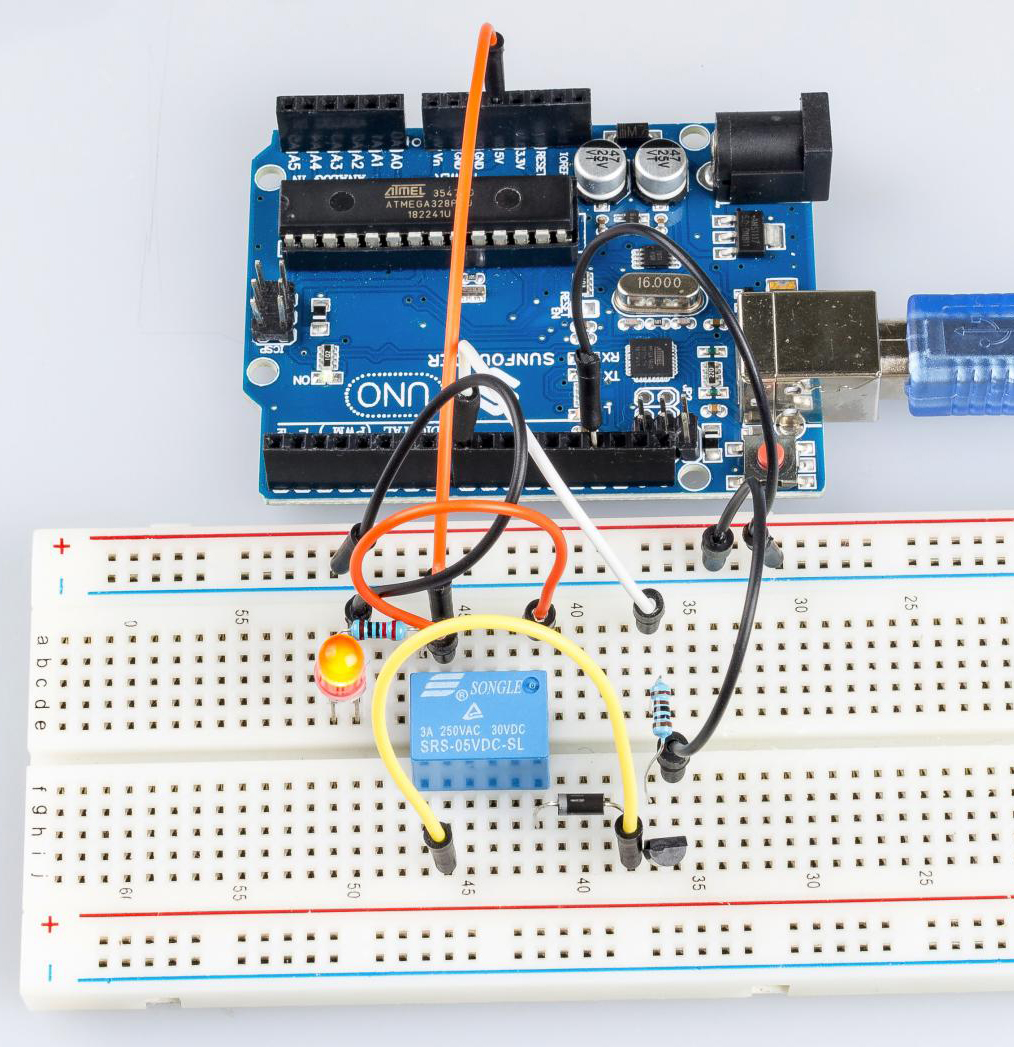
Step 1:Build the circuit
Step 2: Open the code file.
Step 3: Select the Board and Port.
Step 4: Upload the sketch to the board.
Now, send a High level signal, and the relay will close and the LED will light up; send a low one, and it will open and the LED will go out. In addition, you can hear a tick-tock caused by breaking the normally close contact and closing the normally open one.
Code
Code Analysis
void loop()

{

  digitalWrite(relayPin, HIGH); //drive relay closure conduction

  delay(1000); //wait for a second

  digitalWrite(relayPin, LOW); //drive the relay is closed off

  delay(1000); //wait for a second

}
The code in this experiment is simple. First, set relayPin as HIGH level and the LED connected to the relay will light up. Then set relayPin as LOW level and the LED goes out.