Note
Hello, welcome to the SunFounder Raspberry Pi & Arduino & ESP32 Enthusiasts Community on Facebook! Dive deeper into Raspberry Pi, Arduino, and ESP32 with fellow enthusiasts.
Why Join?
Expert Support: Solve post-sale issues and technical challenges with help from our community and team.
Learn & Share: Exchange tips and tutorials to enhance your skills.
Exclusive Previews: Get early access to new product announcements and sneak peeks.
Special Discounts: Enjoy exclusive discounts on our newest products.
Festive Promotions and Giveaways: Take part in giveaways and holiday promotions.
👉 Ready to explore and create with us? Click [here] and join today!
Lesson 1 Blinking LED
Introduction
You should’ve learnt how to install Arduino IDE and add libraries before. Now you can start with a simple experiment to learn the basic operation and code in the IDE.
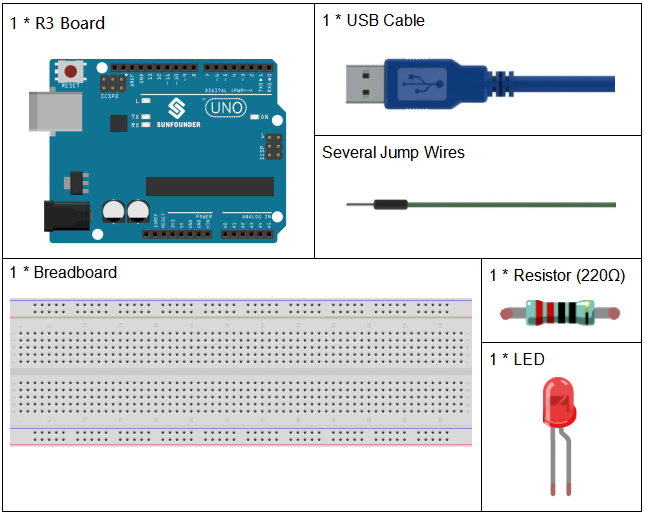
Components
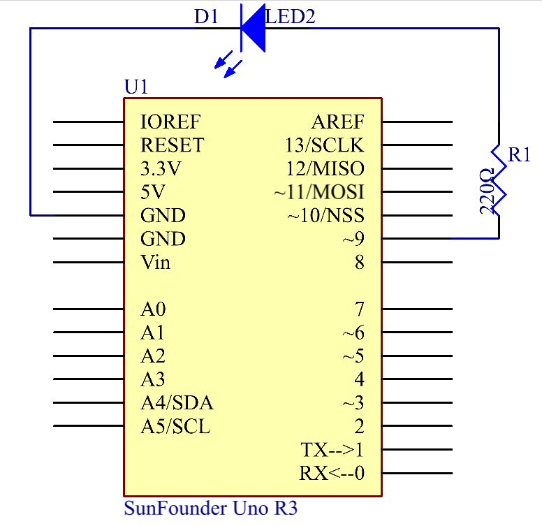
Schematic Diagram
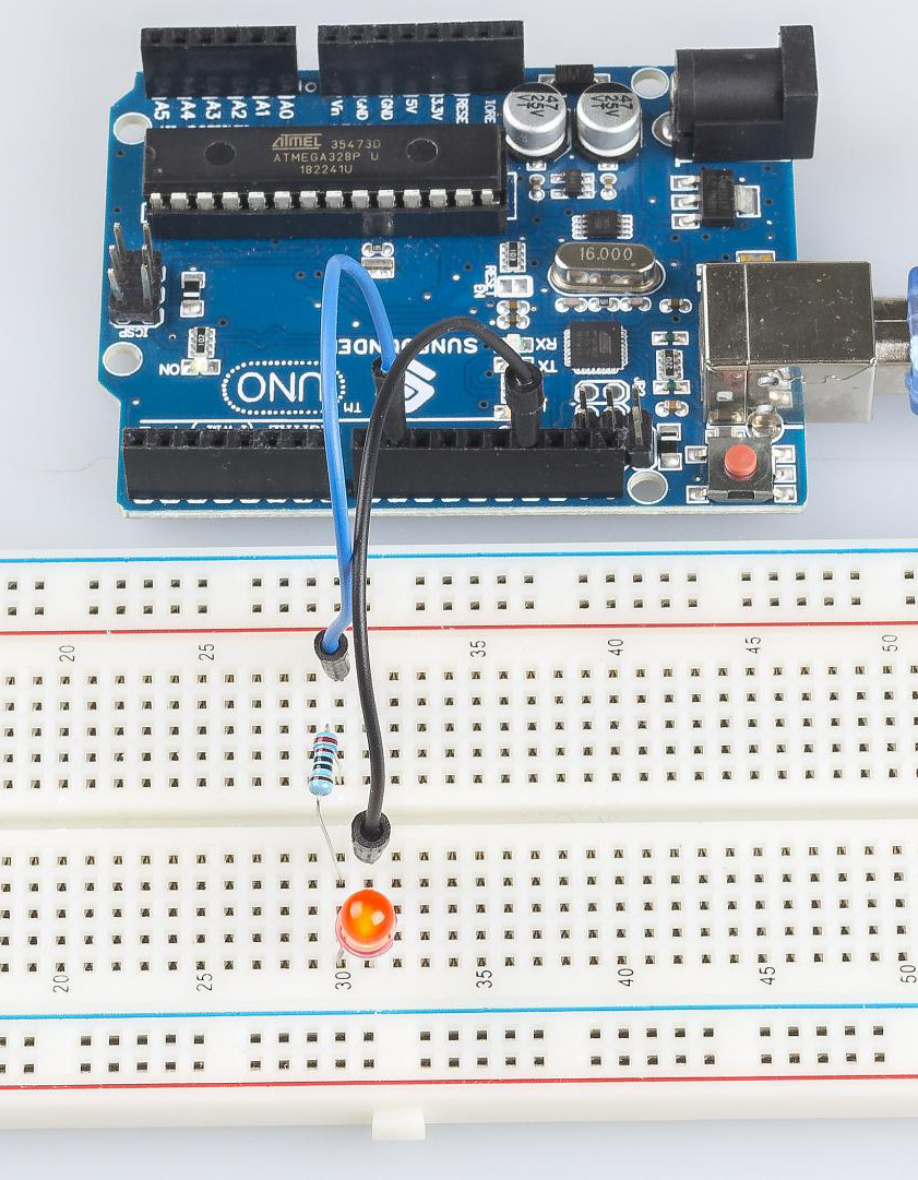
Connect one end of the 220ohm resistor to pin 9 of the Uno and the other end to the anode (the long pin) of the LED, and the cathode (the short pin) of the LED to GND. When the pin 9 outputs high level, the current gets through the current limiting resistor to the anode of the LED. And since the cathode of the LED is connected to GND, the LED will light up. When pin 9 outputs low level, the LED goes out.
Experimental Procedures
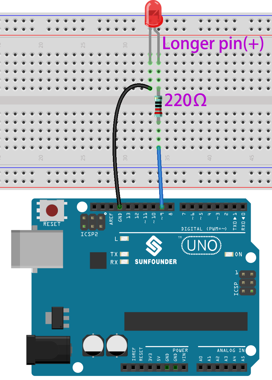
Step 1: Build the circuit (the pin with a curve is the anode of the LED).
Then plug the board into the computer with a 5V USB cable.
Step 2: Open the Lesson_3_Blinking_LED.ino code file in the path of
SunFounder Uno Kit\Code\Lesson_3_Blinking_LED
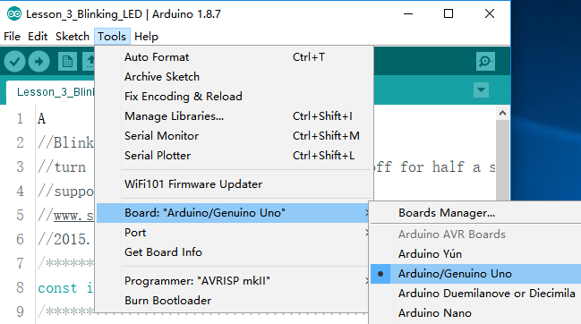
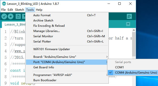
Step 3: Select the Board and Port
Before uploading the code, you need to select the Board and Port. Click Tools -> Board and select Arduino/Genuino Uno.
Then select Tools -> Port. Your port should be different from mine.
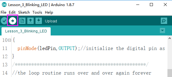
Step 4: Upload the sketch to the SunFounder Uno board
Click the Upload icon to upload the code to the control board.
If “Done uploading” appears at the bottom of the window, it means the sketch has been successfully uploaded.
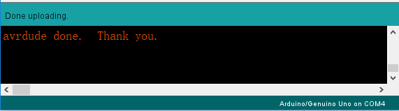
You should now see the LED blinking.
Code
Code Analysis
Define variables
const int ledPin = 9; //the number of the LED pin
You should define every variable before using in case of making
mistakes. This line defines a constant variable ledPin for the pin 9.
In the following code, ledPin stands for pin 9. You can also directly
use pin 9 instead.
setup() function
A typical Arduino program consists of two subprograms: setup() for
initialization and loop() which contains the main body of the program.
The setup() function is usually used to initialize the digital pins
and set them as input or output as well as the baud rate of the serial
communication.
The loop() function contains what the MCU will run circularly. It will
not stop unless something happens like power outages.
void setup()

{

    pinMode(ledPin,OUTPUT);//initialize the digital pin as an output

}
The setup() function here sets the ledPin as OUTPUT.
pinMode(Pin): Configures the specified pin to behave either as an input or an output.
The void before the setup means that this function will not return a value. Even when no pins need to be initialized, you still need this function. Otherwise there will be errors in compiling.
loop function
void loop()

{

    digitalWrite(ledPin,HIGH); //turn the LED on

    delay(500); //wait for half a second

    digitalWrite(ledPin,LOW); //turn the LED off

    delay(500); //wait for half a second

}
This program is to set ledPin as HIGH to turn on the LED, with a delay
of 500ms. Set ledPin as LOW to turn the LED off and also delay 500ms.
The MCU will run this program repeatedly and you will see that the LED
brightens for 500ms and then dims for 500ms. This on/off alternation
will not stop until the control board runs out of energy.
digitWrite(Pin): Write
a HIGH or
a LOW value to a
digital pin. When this pin has been set as output in pinModel(), its
voltage will be set to the corresponding value: 5V (or 3.3V on 3.3V
boards) for HIGH, 0V (ground) for LOW.
Experiment Summary
Through this experiment, you have learned how to turn on an LED. You can
also change the blinking frequency of the LED by changing the num
value in the delay function delay (num). For example, change it to
delay (250) and you will find that the LED blinks more quickly.