Note
Hello, welcome to the SunFounder Raspberry Pi & Arduino & ESP32 Enthusiasts Community on Facebook! Dive deeper into Raspberry Pi, Arduino, and ESP32 with fellow enthusiasts.
Why Join?
Expert Support: Solve post-sale issues and technical challenges with help from our community and team.
Learn & Share: Exchange tips and tutorials to enhance your skills.
Exclusive Previews: Get early access to new product announcements and sneak peeks.
Special Discounts: Enjoy exclusive discounts on our newest products.
Festive Promotions and Giveaways: Take part in giveaways and holiday promotions.
👉 Ready to explore and create with us? Click [here] and join today!
2.11 Swinging Servo
In this kit, in addition to LED and passive buzzer, there is also a device controlled by PWM signal, Servo.
Servo is a position (angle) servo device, which is suitable for those control systems that require constant angle changes and can be maintained. It has been widely used in high-end remote control toys, such as airplanes, submarine models, and remote control robots.
Now, try to make the servo sway!
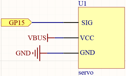
Schematic
Wiring
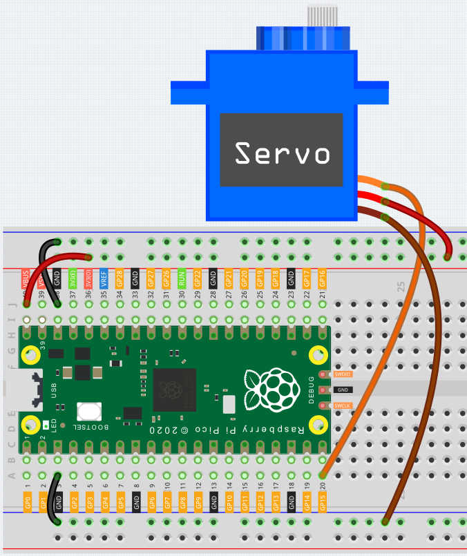
Press the Servo Arm into the Servo output shaft. If necessary, fix it with screws.
Connect VBUS (not 3V3) and GND of Pico to the power bus of the breadboard.
Connect the red lead of the servo to the positive power bus with a jumper.
Connect the yellow lead of the servo to the GP15 pin with a jumper wire.
Connect the brawn lead of the servo to the negative power bus with a jumper wire.
Code
When the program is running, we can see the Servo Arm swinging back and forth from 0° to 180°. The program will always run because of the while True loop, we need to press the Stop key to end the program.
import machine
import utime

servo = machine.PWM(machine.Pin(15))
servo.freq(50)

def interval_mapping(x, in_min, in_max, out_min, out_max):
    return (x - in_min) * (out_max - out_min) / (in_max - in_min) + out_min

def servo_write(pin,angle):
    pulse_width=interval_mapping(angle, 0, 180, 0.5,2.5)
    duty=int(interval_mapping(pulse_width, 0, 20, 0,65535))
    pin.duty_u16(duty)

while True:
    for angle in range(180):
        servo_write(servo,angle)
        utime.sleep_ms(20)
    for angle in range(180,-1,-1):
        servo_write(servo,angle)
        utime.sleep_ms(20)
How it works?
We defined the servo_write() function to make the servo run.
This function has two parameters:
pin, the GPIO pin that controls the servo.
Angle, the angle of the shaft output.
In this function, interval_mapping() is called to map the angle range 0 ~ 180 to the pulse width range 0.5 ~ 2.5ms.
pulse_width=interval_mapping(angle, 0, 180, 0.5,2.5)
Why is it 0.5~2.5? This is determined by the working mode of the Servo.
Next, convert the pulse width from period to duty. Since duty_u16() cannot have decimals when used (the value cannot be a float type), we used int() to force the duty to be converted to an int type.
duty=int(interval_mapping(pulse_width, 0, 20, 0,65535))
Finally, write the duty value into duty_u16().