Note
Hello, welcome to the SunFounder Raspberry Pi & Arduino & ESP32 Enthusiasts Community on Facebook! Dive deeper into Raspberry Pi, Arduino, and ESP32 with fellow enthusiasts.
Why Join?
Expert Support: Solve post-sale issues and technical challenges with help from our community and team.
Learn & Share: Exchange tips and tutorials to enhance your skills.
Exclusive Previews: Get early access to new product announcements and sneak peeks.
Special Discounts: Enjoy exclusive discounts on our newest products.
Festive Promotions and Giveaways: Take part in giveaways and holiday promotions.
👉 Ready to explore and create with us? Click [here] and join today!
2.16 7-Segment Display
7-Segment Display can be seen everywhere in life. For example, on an air conditioner, it can be used to display temperature; on a traffic indicator, it can be used to display a timer.
The 7-Segment Display is essentially a device packaged by 8 LEDs, of which 7 strip-shaped LEDs form an “8” shape, and there is a slightly smaller dotted LED as a decimal point. These LEDs are marked as a, b, c, d, e, f, g, and dp. They have their own anode pins and share cathodes. Their pin locations are shown in the figure below.
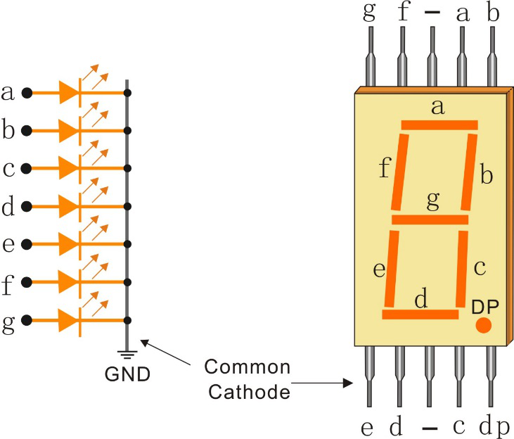
This means that it needs to be controlled by 8 digital signals at the same time to fully work and the 74HC595 can do this.
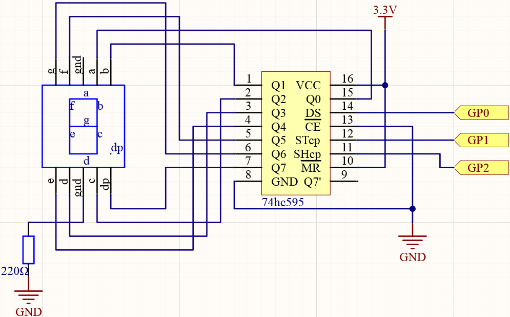
Schematic
Wiring
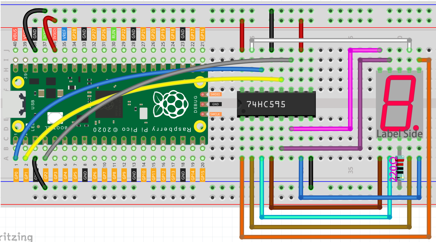
Connect 3V3 and GND of Pico to the power bus of the breadboard.
Insert 74HC595 across the middle gap into the breadboard.
Connect the GP0 pin of Pico to the DS pin (pin 14) of 74HC595 with a jumper wire.
Connect the GP1 pin of Pico to the STcp pin (12-pin) of 74HC595.
Connect the GP2 pin of Pico to the SHcp pin (pin 11) of 74HC595.
Connect the VCC pin (16 pin) and MR pin (10 pin) on the 74HC595 to the positive power bus.
Connect the GND pin (8-pin) and CE pin (13-pin) on the 74HC595 to the negative power bus.
Insert the LED Segment Display into the breadboard, and connect a 220Ω resistor in series with the GND pin to the negative power bus.
Note
The color ring of the 220 ohm resistor is red, red, black, black and brown.
Follow the table below to connect the 74hc595 and LED Segment Display.
Wiring 74HC595
LED Segment Display
Q0
a
Q1
b
Q2
c
Q3
d
Q4
e
Q5
f
Q6
g
Q7
dp
Code
import machine
import time

SEGCODE = [0x3f,0x06,0x5b,0x4f,0x66,0x6d,0x7d,0x07,0x7f,0x6f]

sdi = machine.Pin(0,machine.Pin.OUT)
rclk = machine.Pin(1,machine.Pin.OUT)
srclk = machine.Pin(2,machine.Pin.OUT)

def hc595_shift(dat):
    rclk.low()
    time.sleep_ms(5)
    for bit in range(7, -1, -1):
        srclk.low()
        time.sleep_ms(5)
        value = 1 & (dat >> bit)
        sdi.value(value)
        time.sleep_ms(5)
        srclk.high()
        time.sleep_ms(5)
    time.sleep_ms(5)
    rclk.high()
    time.sleep_ms(5)

while True:
    for num in range(10):
        hc595_shift(SEGCODE[num])
        time.sleep_ms(500)
When the program is running, you will be able to see the LED Segment Display display 0~9 in sequence.
How it works?
hc595_shift() will make 74HC595 output 8 digital signals.
It outputs the last bit of the binary number to Q0, and the output of the first bit to Q7. In other words, writing the binary number “00000001” will make Q0 output high level and Q1~Q7 output low level.
Suppose that the 7-segment Display display the number “1”, we need to write a high level for b, c, and write a low level for a, d, e, f, g, and dg. That is, the binary number “00000110” needs to be written. For readability, we will use hexadecimal notation as “0x06”.
Similarly, we can also make the LED Segment Display display other numbers in the same way. The following table shows the codes corresponding to these numbers.
Numbers |
Binary Code |
Hex Code |
|---|---|---|
0 |
00111111 |
0x3f |
1 |
00000110 |
0x06 |
2 |
01011011 |
0x5b |
3 |
01001111 |
0x4f |
4 |
01100110 |
0x66 |
5 |
01101101 |
0x6d |
6 |
01111101 |
0x7d |
7 |
00000111 |
0x07 |
8 |
01111111 |
0x7f |
9 |
01101111 |
0x6f |
Write these codes into hc595_shift() to make the LED Segment Display display the corresponding numbers.