Note
Hello, welcome to the SunFounder Raspberry Pi & Arduino & ESP32 Enthusiasts Community on Facebook! Dive deeper into Raspberry Pi, Arduino, and ESP32 with fellow enthusiasts.
Why Join?
Expert Support: Solve post-sale issues and technical challenges with help from our community and team.
Learn & Share: Exchange tips and tutorials to enhance your skills.
Exclusive Previews: Get early access to new product announcements and sneak peeks.
Special Discounts: Enjoy exclusive discounts on our newest products.
Festive Promotions and Giveaways: Take part in giveaways and holiday promotions.
👉 Ready to explore and create with us? Click [here] and join today!
2.12 Turn the Knob
In the previous projects, we have used the digital input on the Pico. For example, a button can change the pin from low level (off) to high level (on). This is a binary working state.
However, Pico can receive another type of input signal: analog input. It can be in any state from fully closed to fully open, and has a range of possible values. The analog input allows the microcontroller to sense the light intensity, sound intensity, temperature, humidity, etc. of the physical world.
Usually, a microcontroller needs an additional hardware to implement analog input-the analogue-to-digital converter (ADC). But Pico itself has a built-in ADC for us to use directly.
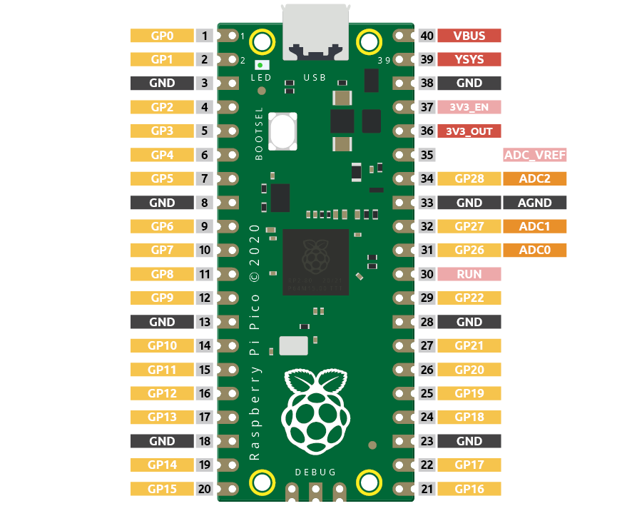
Pico has three GPIO pins that can use analog input, GP26, GP27, GP28. That is, analog channels 0, 1, and 2. In addition, there is a fourth analog channel, which is connected to the built-in temperature sensor and will not be introduced here.
In this project, we try to read the analog value of potentiometer.
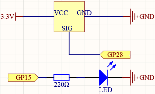
Schematic
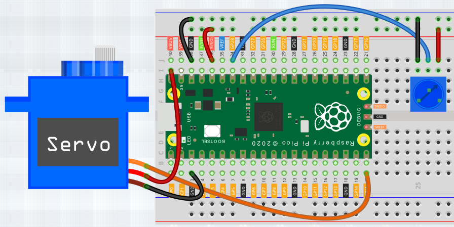
Wiring
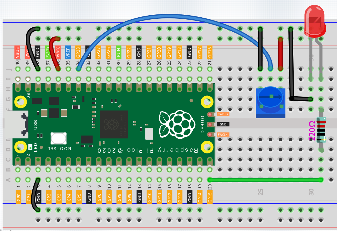
Connect 3V3 and GND of Pico to the power bus of the breadboard.
Insert the potentiometer into the breadboard, its three pins should be in different rows.
Use jumper wires to connect the pins on both sides of the potentiometer to the positive and negative power bus respectively.
Connect the middle pin of the potentiometer to GP28 with a jumper wire.
Connect the anode of the LED to the GP15 pin through a 220Ω resistor, and connect the cathode to the negative power bus.
Code
When the program is running, we can see the analog value currently read by the GP28 pin in the shell. Turn the knob, and the value will change from 0 to 65535. At the same time, the brightness of the LED will increase as the analog value increases.
import machine
import utime

potentiometer = machine.ADC(28)
led = machine.PWM(machine.Pin(15))
led.freq(1000)

while True:
    value=potentiometer.read_u16()
    print(value)
    led.duty_u16(value)
    utime.sleep_ms(200)
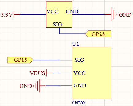
What more?
Let’s use the potentiometer to swing the servo from left to right!
import machine
import utime

potentiometer = machine.ADC(28)
servo = machine.PWM(machine.Pin(15))
servo.freq(50)

def interval_mapping(x, in_min, in_max, out_min, out_max):
    return (x - in_min) * (out_max - out_min) / (in_max - in_min) + out_min

def servo_write(pin,angle):
    pulse_width=interval_mapping(angle, 0, 180, 0.5,2.5)
    duty=int(interval_mapping(pulse_width, 0, 20, 0,65535))
    pin.duty_u16(duty)

while True:
    value=potentiometer.read_u16()
    angle=interval_mapping(value,0,65535,0,180)
    servo_write(servo,angle)
    utime.sleep_ms(200)