Note
Hello, welcome to the SunFounder Raspberry Pi & Arduino & ESP32 Enthusiasts Community on Facebook! Dive deeper into Raspberry Pi, Arduino, and ESP32 with fellow enthusiasts.
Why Join?
Expert Support: Solve post-sale issues and technical challenges with help from our community and team.
Learn & Share: Exchange tips and tutorials to enhance your skills.
Exclusive Previews: Get early access to new product announcements and sneak peeks.
Special Discounts: Enjoy exclusive discounts on our newest products.
Festive Promotions and Giveaways: Take part in giveaways and holiday promotions.
👉 Ready to explore and create with us? Click [here] and join today!
2.15 Microchip - 74HC595
Integrated circuit (integrated circuit) is a kind of miniature electronic device or component, which is represented by the letter “IC” in the circuit.
A certain process is used to interconnect the transistors, resistors, capacitors, inductors and other components and wiring required in a circuit, fabricate on a small or several small semiconductor wafers or dielectric substrates, and then package them in a package , it has become a micro-structure with the required circuit functions; all of the components have been structured as a whole, making electronic components a big step towards micro-miniaturization, low power consumption, intelligence and high reliability.
The inventors of integrated circuits are Jack Kilby (integrated circuits based on germanium (Ge)) and Robert Norton Noyce (integrated circuits based on silicon (Si)).
This kit is equipped with an IC, 74HC595, which can greatly save the use of GPIO pins. Specifically, it can replace 8 pins for digital signal output by writing an 8-bit binary number.
Let’s use it.
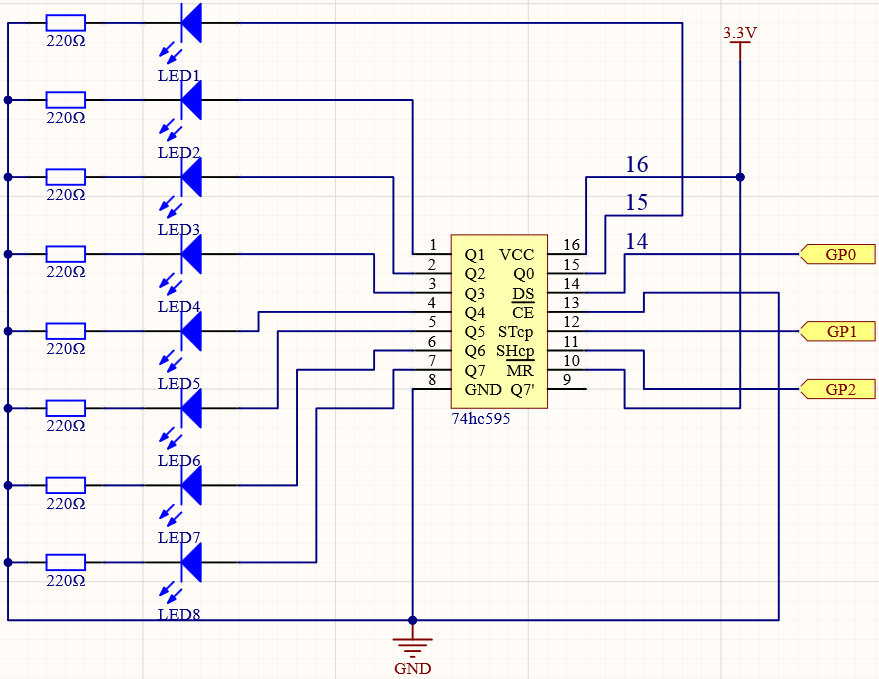
Schematic
Wiring
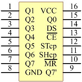
The 74HC595 is a 16-pin IC with a semi-circular notch on one side (usually the left side of the label). With the notch facing upwards, its pins are shown in the diagram below.
Refer to the figure below to build the circuit.
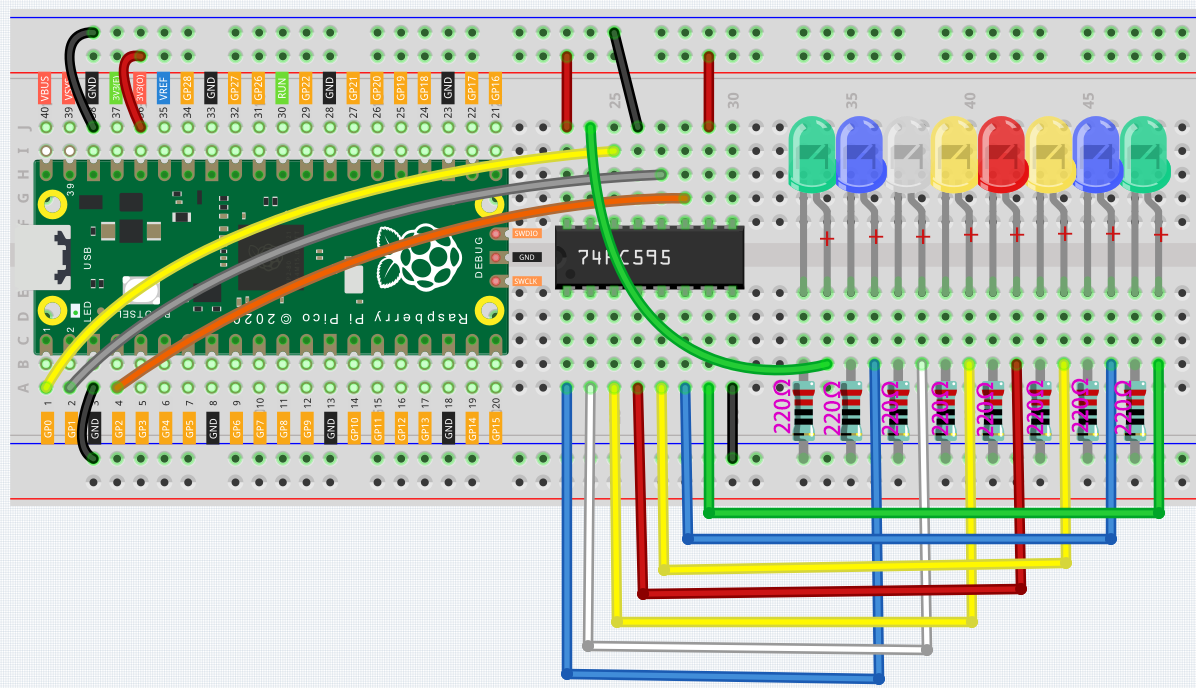
Connect 3V3 and GND of Pico to the power bus of the breadboard.
Insert 74HC595 across the middle gap into the breadboard.
Connect the GP0 pin of Pico to the DS pin (pin 14) of 74HC595 with a jumper wire.
Connect the GP1 pin of Pico to the STcp pin (12-pin) of 74HC595.
Connect the GP2 pin of Pico to the SHcp pin (pin 11) of 74HC595.
Connect the VCC pin (16 pin) and MR pin (10 pin) on the 74HC595 to the positive power bus.
Connect the GND pin (8-pin) and CE pin (13-pin) on the 74HC595 to the negative power bus.
Insert 8 LEDs on the breadboard, and their anode leads are respectively connected to the Q0~Q1 pins (15, 1, 2, 3, 4, 5, 6, 7) of 74HC595.
Connect the cathode leads of the LEDs with a 220Ω resistor in series to the negative power bus.
Code
import machine
import time

sdi = machine.Pin(0,machine.Pin.OUT)
rclk = machine.Pin(1,machine.Pin.OUT)
srclk = machine.Pin(2,machine.Pin.OUT)

def hc595_shift(dat):
    rclk.low()
    time.sleep_ms(5)
    for bit in range(7, -1, -1):
        srclk.low()
        time.sleep_ms(5)
        value = 1 & (dat >> bit)
        sdi.value(value)
        time.sleep_ms(5)
        srclk.high()
        time.sleep_ms(5)
    time.sleep_ms(5)
    rclk.high()
    time.sleep_ms(5)

num = 0

for i in range(16):
    if i < 8:
        num = (num<<1) + 1
    elif i>=8:
        num = (num & 0b01111111)<<1
    hc595_shift(num)
    print("{:0>8b}".format(num))
    time.sleep_ms(200)
When the program is running, num will be written into the 74HC595 chip as an eight-bit binary number to control the on and off of the 8 LEDs.
We can see the current value of num in the shell.
How it works?
hc595_shift() will make 74HC595 output 8 digital signals. It outputs the last bit of the binary number to Q0, and the output of the first bit to Q7. In other words, writing the binary number “00000001” will make Q0 output high level and Q1~Q7 output low level.