Note
Hello, welcome to the SunFounder Raspberry Pi & Arduino & ESP32 Enthusiasts Community on Facebook! Dive deeper into Raspberry Pi, Arduino, and ESP32 with fellow enthusiasts.
Why Join?
Expert Support: Solve post-sale issues and technical challenges with help from our community and team.
Learn & Share: Exchange tips and tutorials to enhance your skills.
Exclusive Previews: Get early access to new product announcements and sneak peeks.
Special Discounts: Enjoy exclusive discounts on our newest products.
Festive Promotions and Giveaways: Take part in giveaways and holiday promotions.
👉 Ready to explore and create with us? Click [here] and join today!
2.8 Fading LED
So far, we have used only two output signals: high level and low level (or called 1 & 0, ON & OFF), which is called digital output. However, in actual use, many devices do not simply ON/OFF to work, for example, adjusting the speed of the motor, adjusting the brightness of the desk lamp, and so on. In the past, a slider that can adjust the resistance was used to achieve this goal, but this is always unreliable and inefficient. Therefore, Pulse width modulation (PWM) has emerged as a feasible solution to such complex problems.
A digital output composed of a high level and a low level is called a pulse. The pulse width of these pins can be adjusted by changing the ON/OFF speed.
Simply put, when we are in a short period (such as 20ms, most people’s visual retention time), Let the LED turn on, turn off, and turn on again, we won’t see it has been turned off, but the brightness of the light will be slightly weaker. During this period, the more time the LED is turned on, the higher the brightness of the LED. In other words, in the cycle, the wider the pulse, the greater the “electric signal strength” output by the microcontroller. This is how PWM controls LED brightness (or motor speed).
There are some points to pay attention to when Pico uses PWM. Let’s take a look at this picture.
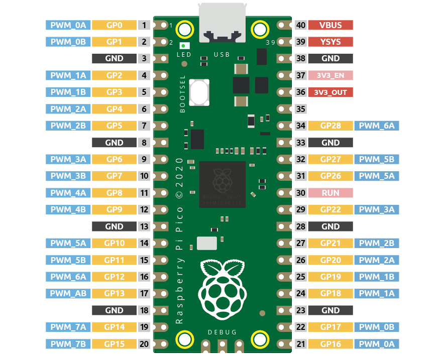
Each GPIO pin of Pico supports PWM, but it actually has a total of 16 independent PWM outputs (instead of 30), distributed between GP0 to GP15 on the left, and the PWM output of the right GPIO is equivalent to the left copy.
What we need to pay attention to is to avoid setting the same PWM channel for different purposes during programming. (For example, GP0 and GP16 are both PWM_0A)
After understanding this knowledge, let us try to achieve the effect of Fading LED.
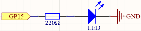
Schematic
Wiring
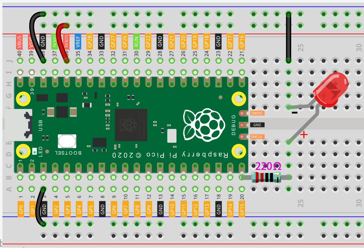
Here we use the GP15 pin of the Pico board.
Connect one end (either end) of the 220 ohm resistor to GP15, and insert the other end into the free row of the breadboard.
Insert the anode lead of the LED into the same row as the end of the 220Ω resistor, and connect the cathode lead across the middle gap of the breadboard to the same row.
Connect the LED cathode to the negative power bus of the breadboard.
Connect the negative power bus to the GND pin of Pico.
Note
The color ring of the 220 ohm resistor is red, red, black, black and brown.
Code
The LED will gradually become brighter as the program runs.
import machine
import utime

led = machine.PWM(machine.Pin(15))
led.freq(1000)

for brightness in range(0,65535,50):
    led.duty_u16(brightness)
    utime.sleep_ms(10)
led.duty_u16(0)
How it works?
Here, we change the brightness of the LED by changing the duty cycle of the GP15’s PWM output. Let’s take a look at these lines.
import machine
import utime

led = machine.PWM(machine.Pin(15))
led.freq(1000)

for brightness in range(0,65535,50):
    led.duty_u16(brightness)
    utime.sleep_ms(10)
led.duty_u16(0)
led = machine.PWM(machine.Pin(15))sets the GP15 pin as PWM output.The line
led.freq(1000)is used to set the PWM frequency, here it is set to 1000Hz, which means 1ms (1/1000) is a cycle. The PWM frequency can be adjusted, for example, the steering wheel needs to work at 50Hz, the passive buzzer can change the tone by changing the PWM frequency. However, there is no limit when using LEDs alone, we set it to 1000Hz.The
led.duty_u16()line is used to set the duty cycle, which is a 16-bit interger(2^16=65536). When we assign a 0 to this function, the duty cycle is 0%, and each cycle has 0% of the time to output a high level, in other words, turn off all pulses. When the value is 65535, the duty cycle is 100%, that is, the complete pulse is turned on, and the result is equal to ‘1’ as a digital output. If it is 32768, it will turn on half a pulse, and the brightness of the LED will be half of that when it is fully turned on.