Note
Hello, welcome to the SunFounder Raspberry Pi & Arduino & ESP32 Enthusiasts Community on Facebook! Dive deeper into Raspberry Pi, Arduino, and ESP32 with fellow enthusiasts.
Why Join?
Expert Support: Solve post-sale issues and technical challenges with help from our community and team.
Learn & Share: Exchange tips and tutorials to enhance your skills.
Exclusive Previews: Get early access to new product announcements and sneak peeks.
Special Discounts: Enjoy exclusive discounts on our newest products.
Festive Promotions and Giveaways: Take part in giveaways and holiday promotions.
👉 Ready to explore and create with us? Click [here] and join today!
1.1.5 4-Digit 7-Segment Display
Introduction
Next, follow me to try to control the 4-digit 7-segment display.
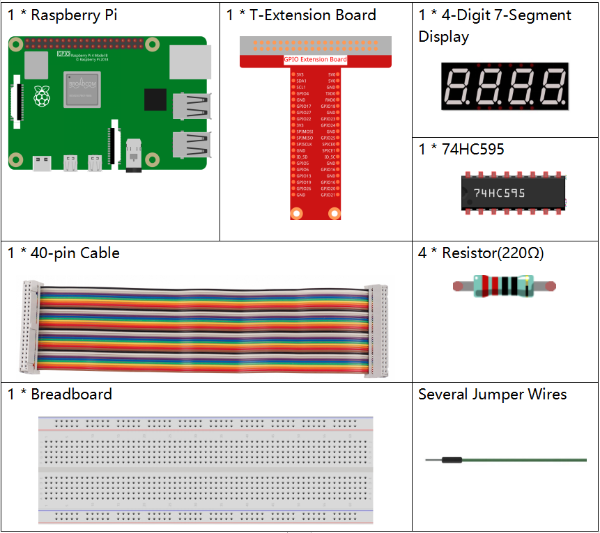
Required Components
In this project, we need the following components.
It’s definitely convenient to buy a whole kit, here’s the link:
Name |
ITEMS IN THIS KIT |
LINK |
|---|---|---|
Raphael Kit |
337 |
You can also buy them separately from the links below.
COMPONENT INTRODUCTION |
PURCHASE LINK |
|---|---|
- |
|
Note
In this projiect, for the 4-Digit 7-Segment Display we should use BS model,if you use AS model it may not light up.
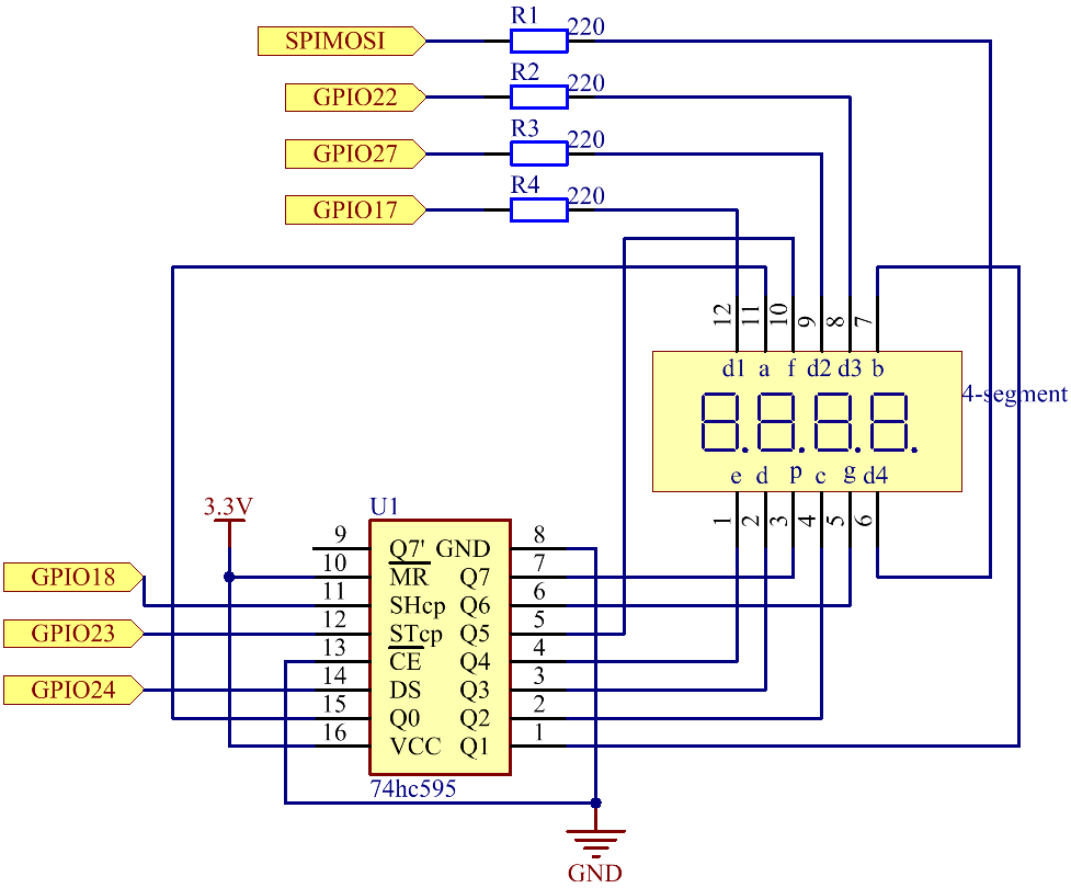
Schematic Diagram
Experimental Procedures
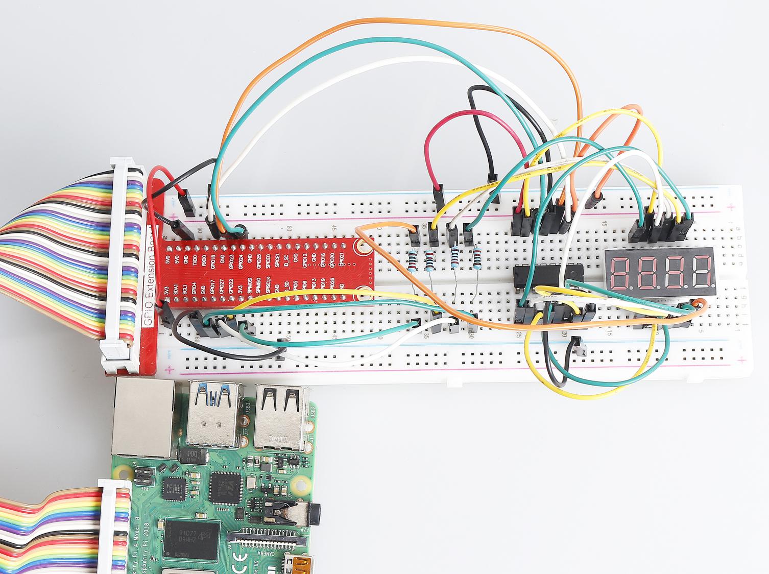
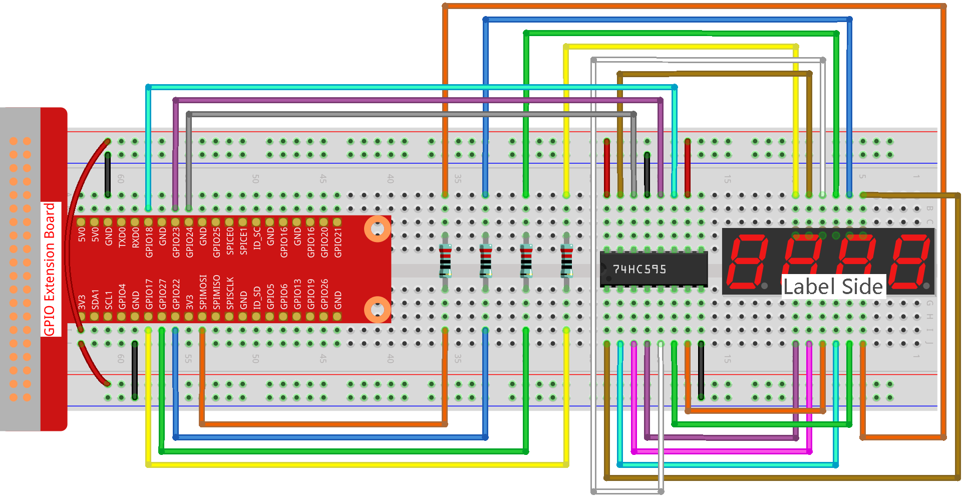
Step 1: Build the circuit.
Step 2: Go to the folder of the code.
cd ~/raphael-kit/nodejs/
Step 3: Run the code.
sudo node 4_digit_7_segment_display.js
After the code runs, the program takes a count, increasing by 1 per second, and the 4-digit 7-segment display displays the count.
Code
const Gpio = require('pigpio').Gpio;

var counter = 0;

const number = [0xc0, 0xf9, 0xa4, 0xb0, 0x99, 0x92, 0x82, 0xf8, 0x80, 0x90]; //for BS

const SDI = new Gpio(24, { mode: Gpio.OUTPUT });
const RCLK = new Gpio(23, { mode: Gpio.OUTPUT });
const SRCLK = new Gpio(18, { mode: Gpio.OUTPUT });

const pin1 = new Gpio(10, { mode: Gpio.OUTPUT });
const pin2 = new Gpio(22, { mode: Gpio.OUTPUT });
const pin3 = new Gpio(27, { mode: Gpio.OUTPUT });
const pin4 = new Gpio(17, { mode: Gpio.OUTPUT });
const placePin = [pin1, pin2, pin3, pin4];

function clearDisplay() {
    hc595_shift(0xff); //for BS
}

function hc595_shift(dat) {
    for (let j = 0; j < 8; j++) {
        let code = 0x80 & (dat << j);
        if (code != 0) {
            code = 1;
        }
        SDI.digitalWrite(code);
        SRCLK.trigger(1,1);
    }
    RCLK.trigger(1,1);
}

function pickDigit(digit) {
    for(let i=0;i<4;i++){
        placePin[i].digitalWrite(0);
    }
    placePin[digit].digitalWrite(1);
}


let digit = -1
setInterval(() => {
    digit = (digit +1)% 4
    clearDisplay();
    pickDigit(digit);
    switch(digit){
        case 0:
            hc595_shift(number[Math.floor(counter % 10)]);
            break;
        case 1:
            hc595_shift(number[Math.floor(counter % 100 / 10)]);
            break;
        case 2:
            hc595_shift(number[Math.floor(counter % 1000 / 100)]);
            break;
        case 3:
            hc595_shift(number[Math.floor(counter % 10000 / 1000)]);
            break;
    }
}, 5);

setInterval(() => {
    counter++;
}, 1000);
Code Explanation
const pin1 = new Gpio(10, {mode: Gpio.OUTPUT});
const pin2 = new Gpio(25, {mode: Gpio.OUTPUT});
const pin3 = new Gpio(27, {mode: Gpio.OUTPUT});
const pin4 = new Gpio(17, {mode: Gpio.OUTPUT});
const placePin = [pin1,pin2,pin3,pin4];
Initialize pins 10, 25, 27, and 17 as output modes and place them in the array placePin to facilitate control of the common anode of the four-digit 7-segment display.
const number = [0xc0, 0xf9, 0xa4, 0xb0, 0x99, 0x92, 0x82, 0xf8, 0x80, 0x90];
Define a constant array number to represent the hexadecimal segment code from 0 to 9 (common anode).
function clearDisplay() {
    hc595_shift(0xff);
}
Write 0xff to turn off the digital tube.
function pickDigit(digit) {
    for(let i=0;i<4;i++){
        placePin[i].digitalWrite(0);
    }
    placePin[digit].digitalWrite(1);
}
Select the place of the value. there is only one place that should be enable each time. The enabled place will be written high.
let digit = -1
setInterval(() => {
    digit = (digit +1)% 4
    clearDisplay();
    pickDigit(digit);
    switch(digit){
        case 0:
            hc595_shift(number[Math.floor(counter % 10)]);
            break;
        case 1:
            hc595_shift(number[Math.floor(counter % 100 / 10)]);
            break;
        case 2:
            hc595_shift(number[Math.floor(counter % 1000 / 100)]);
            break;
        case 3:
            hc595_shift(number[Math.floor(counter % 10000 / 1000)]);
            break;
    }
}, 5);
this code is used to set the number displayed on the 4-digit 7-segment Dispaly.
First, start the fourth segment display, write the single-digit number. Then start the third segment display, and type in the tens digit; after that, start the second and the first segment display respectively, and write the hundreds and thousands digits respectively. Because the refreshing speed is very fast, we see a complete four-digit display.
setInterval(() => {
    counter++;
}, 1000);
Add one to the counter
(the four-digit digital tube displays the number plus one)
every second that passes.
Phenomenon Picture