Note
Hello, welcome to the SunFounder Raspberry Pi & Arduino & ESP32 Enthusiasts Community on Facebook! Dive deeper into Raspberry Pi, Arduino, and ESP32 with fellow enthusiasts.
Why Join?
Expert Support: Solve post-sale issues and technical challenges with help from our community and team.
Learn & Share: Exchange tips and tutorials to enhance your skills.
Exclusive Previews: Get early access to new product announcements and sneak peeks.
Special Discounts: Enjoy exclusive discounts on our newest products.
Festive Promotions and Giveaways: Take part in giveaways and holiday promotions.
👉 Ready to explore and create with us? Click [here] and join today!
1.1.4 7-segment Display
Introduction
Let’s try to drive a 7-segment display to show a figure from 0 to 9 and A to F.
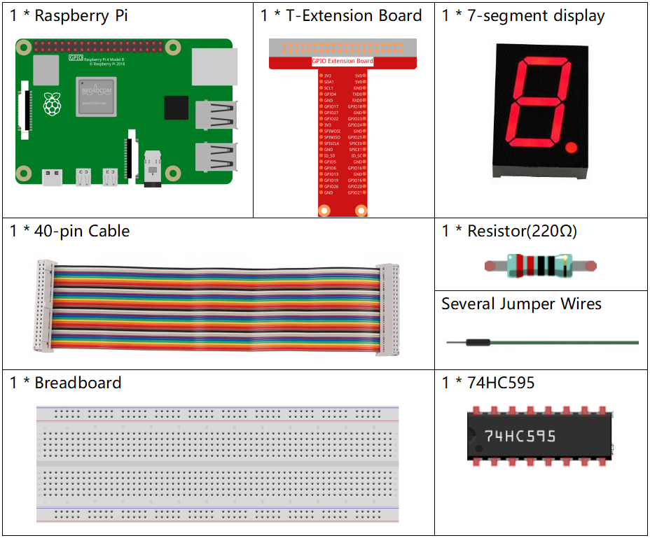
Required Components
In this project, we need the following components.
It’s definitely convenient to buy a whole kit, here’s the link:
Name |
ITEMS IN THIS KIT |
LINK |
|---|---|---|
Raphael Kit |
337 |
You can also buy them separately from the links below.
COMPONENT INTRODUCTION |
PURCHASE LINK |
|---|---|
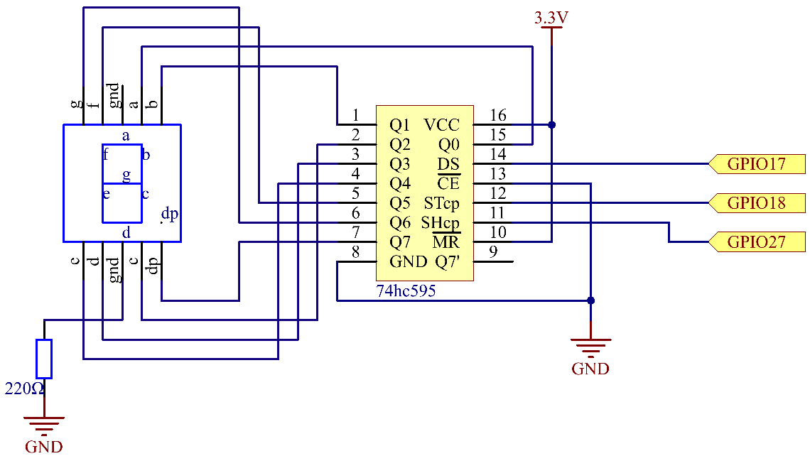
Schematic Diagram
Connect pin ST_CP of 74HC595 to Raspberry Pi GPIO18, SH_CP to GPIO27, DS to GPIO17, parallel output ports to 8 segments of the LED segment display. Input data in DS pin to shift register when SH_CP (the clock input of the shift register) is at the rising edge, and to the memory register when ST_CP (the clock input of the memory) is at the rising edge. Then you can control the states of SH_CP and ST_CP via the Raspberry Pi GPIOs to transform serial data input into parallel data output so as to save Raspberry Pi GPIOs and drive the display.
Experimental Procedures
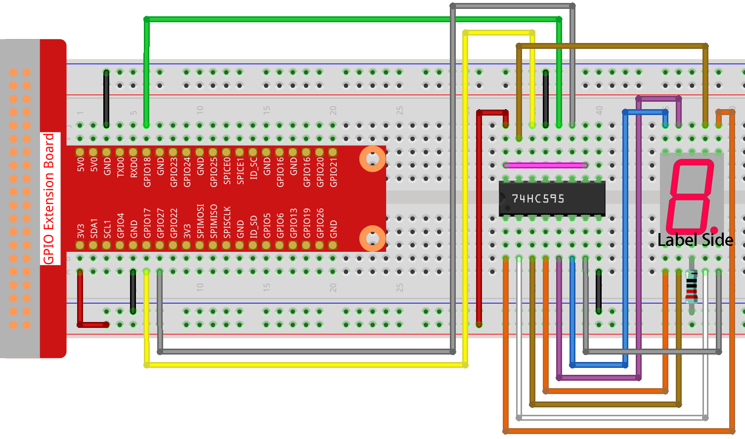
Step 1: Build the circuit.
Step 2: Go to the folder of the code.
cd ~/raphael-kit/nodejs/
Step 3: Run the code.
sudo node 7-segment_display.js
After the code runs, you’ll see the 7-segment display display 0-9, A-F.
Code
const Gpio = require('pigpio').Gpio;

const segCode = [0x3f, 0x06, 0x5b, 0x4f, 0x66, 0x6d, 0x7d, 0x07, 0x7f, 0x6f, 0x77, 0x7c, 0x39, 0x5e, 0x79, 0x71];

const SDI = new Gpio(17, { mode: Gpio.OUTPUT });
const RCLK = new Gpio(18, { mode: Gpio.OUTPUT });
const SRCLK = new Gpio(27, { mode: Gpio.OUTPUT });

function hc595_shift(dat) {
    for (let j = 0; j < 8; j++) {
        let code = 0x80 & (dat << j);
        if (code != 0) {
            code = 1;
        }
        SDI.digitalWrite(code);
        SRCLK.trigger(1,1);
    }
    RCLK.trigger(1,1);
}

let index = -1;
setInterval(() => {
    index = (index+1)%16;
    hc595_shift(segCode[index]);
}, 1000);
Code Explanation
const segCode = [0x3f,0x06,0x5b,0x4f,0x66,0x6d,0x7d,0x07,0x7f,0x6f,0x77,0x7c,0x39,0x5e,0x79,0x71];
Define a hexadecimal (common cathode) segment code array from 0 to F.
const SDI = new Gpio(17, { mode: Gpio.OUTPUT });
const RCLK = new Gpio(18, { mode: Gpio.OUTPUT });
const SRCLK = new Gpio(27, { mode: Gpio.OUTPUT });
Initialize pins 17, 18, and 27 as output mode, and copy them to SDI, RCLK, and SRCLK respectively.
function hc595_shift(dat) {
    for (let j = 0; j < 8; j++) {
        let code = 0x80 & (dat << j);
        if (code != 0) {
            code = 1;
        }
        SDI.digitalWrite(code);
        SRCLK.trigger(1,1);
    }
    RCLK.trigger(1,1);
}
Implement a hc595_shift function to convert the fields in the array segCode into numbers
and display them on the digital tube.
let code = 0x80 & (dat << j);
if (code != 0) {
    code = 1;
}
SDI.digitalWrite(code);
Assign the dat data to SDI(DS) by bits. Here we assume dat=0x3f(0011 1111, when j=2, 0x3f will shift right(<<) 2 bits. 1111 1100 (0x3f << 2) & 1000 0000 (0x80) = 1000 0000, is true. At this time, 1 is written to SDI.
SRCLK.trigger(1,1);
Generate a rising edge pulse and move the DS data to the shift register.
trigger(pulseLen, level)pulseLen - pulse length in microseconds (1 - 100)
level - 0 or 1
Sends a trigger pulse to the GPIO. The GPIO is set to level for pulseLen microseconds and then reset to not level.
RCLK.trigger(1,1);
Generate a rising edge pulse and move the data from the shift register to the storage register.
let index = -1;
setInterval(() => {
    index = (index+1)%16;
    hc595_shift(segCode[index]);
}, 1000);
Finally, use the function hc595_shift() to convert the fields in segCode
and display them through the digital tube.
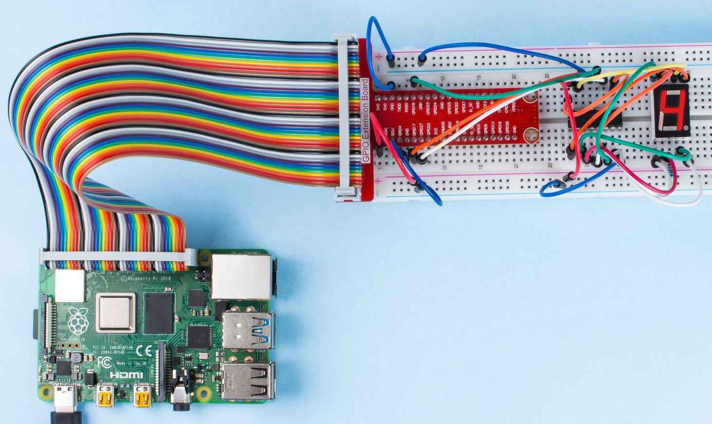
Phenomenon Picture