Note
Hello, welcome to the SunFounder Raspberry Pi & Arduino & ESP32 Enthusiasts Community on Facebook! Dive deeper into Raspberry Pi, Arduino, and ESP32 with fellow enthusiasts.
Why Join?
Expert Support: Solve post-sale issues and technical challenges with help from our community and team.
Learn & Share: Exchange tips and tutorials to enhance your skills.
Exclusive Previews: Get early access to new product announcements and sneak peeks.
Special Discounts: Enjoy exclusive discounts on our newest products.
Festive Promotions and Giveaways: Take part in giveaways and holiday promotions.
👉 Ready to explore and create with us? Click [here] and join today!
1.1.2 RGB LED
Introduction
In this project, we will control an RGB LED to flash various colors.
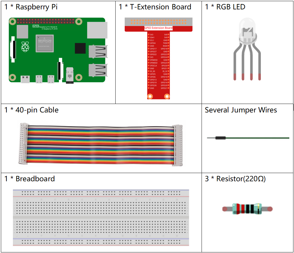
Required Components
In this project, we need the following components.
It’s definitely convenient to buy a whole kit, here’s the link:
Name |
ITEMS IN THIS KIT |
LINK |
|---|---|---|
Raphael Kit |
337 |
You can also buy them separately from the links below.
COMPONENT INTRODUCTION |
PURCHASE LINK |
|---|---|
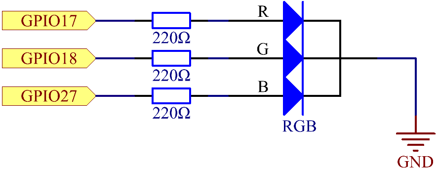
Schematic Diagram
After connecting the pins of R, G, and B to a current limiting resistor, connect them to the GPIO17, GPIO18, and GPIO27 respectively. The longest pin (GND) of the LED connects to the GND of the Raspberry Pi. When the three pins are given different PWM values, the RGB LED will display different colors.
Experimental Procedures
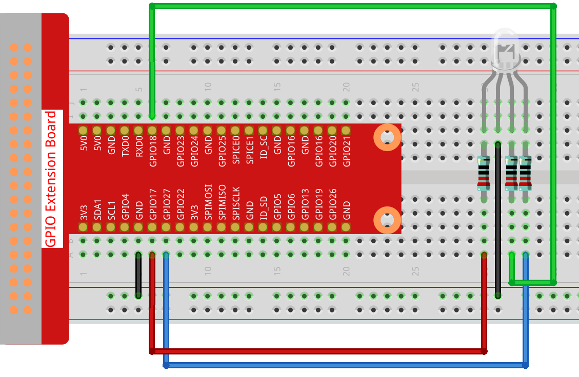
Step 1: Build the circuit.
Step 2: Go to the folder of the code.
cd ~/raphael-kit/nodejs/
Step 3: Run the code.
sudo node rgb_led.js
After the code runs, you will see that RGB displays red, green, blue, yellow, pink, and cyan.
Code
const Gpio = require('pigpio').Gpio;
const ledred = new Gpio(17, { mode: Gpio.OUTPUT });
const ledgreen = new Gpio(18, { mode: Gpio.OUTPUT });
const ledblue = new Gpio(27, { mode: Gpio.OUTPUT });

function colorset(r, g, b) {
    ledred.pwmWrite(r);
    ledgreen.pwmWrite(g);
    ledblue.pwmWrite(b);
}

var color_index = -1;

setInterval(() => {
color_index += 1;
switch (color_index) {
    case 0:
        colorset(0xff, 0x00, 0xFF);
        break;
    case 1:
        colorset(0x00, 0xff, 0x00);
        break;
    case 2:
        colorset(0x00, 0x00, 0xff);
        break;
    case 3:
        colorset(0xff, 0xff, 0x00);
        break;
    case 4:
        colorset(0xff, 0x00, 0xff);
        break;
    case 5:
        colorset(0xc0, 0xff, 0x3e);
        break;
    default:
        color_index=-1;
    }
}, 500);
Code Explanation
const ledred = new Gpio(17,{mode: Gpio.OUTPUT});
const ledgreen = new Gpio(18,{mode: Gpio.OUTPUT});
const ledblue = new Gpio(27,{mode: Gpio.OUTPUT});
Initialize pins 17, 18, and 27 to output mode, and assign them to the constants ledred, ledgreen, and ledblue respectively.
function colorset(r,g,b){
    ledred.pwmWrite(r);
    ledgreen.pwmWrite(g);
    ledblue.pwmWrite(b);
}
Implement a colorset(r,g,b) function, which is used to write pulse values to pins 17, 18, 27. The Gpio library encapsulates the function pwmWrite() to write to pins Pulse value, the value is 0x00 to 0xff. Then you can write RGB values to the RGB LED through the colorset(r,g,b) function, so that it can display a variety of colors.
Note
For questions about RGB, please refer to the website: https://www.rapidtables.com/web/color/RGB_Color.html
var color_index = -1;

setInterval(() => {
color_index += 1;
switch (color_index) {
    case 0:
        colorset(0xff, 0x00, 0xFF);
        break;
    case 1:
        colorset(0x00, 0xff, 0x00);
        break;
    case 2:
        colorset(0x00, 0x00, 0xff);
        break;
    case 3:
        colorset(0xff, 0xff, 0x00);
        break;
    case 4:
        colorset(0xff, 0x00, 0xff);
        break;
    case 5:
        colorset(0xc0, 0xff, 0x3e);
        break;
    default:
        color_index=-1;
    }
}, 500);
The RGB LED is controlled by colorset() executed every 500ms.
A switch case is used here to select the color emitted by the RGB LEDs.
Since color_index is changed by one every cycle, the color of this one RGB LED will change in order.
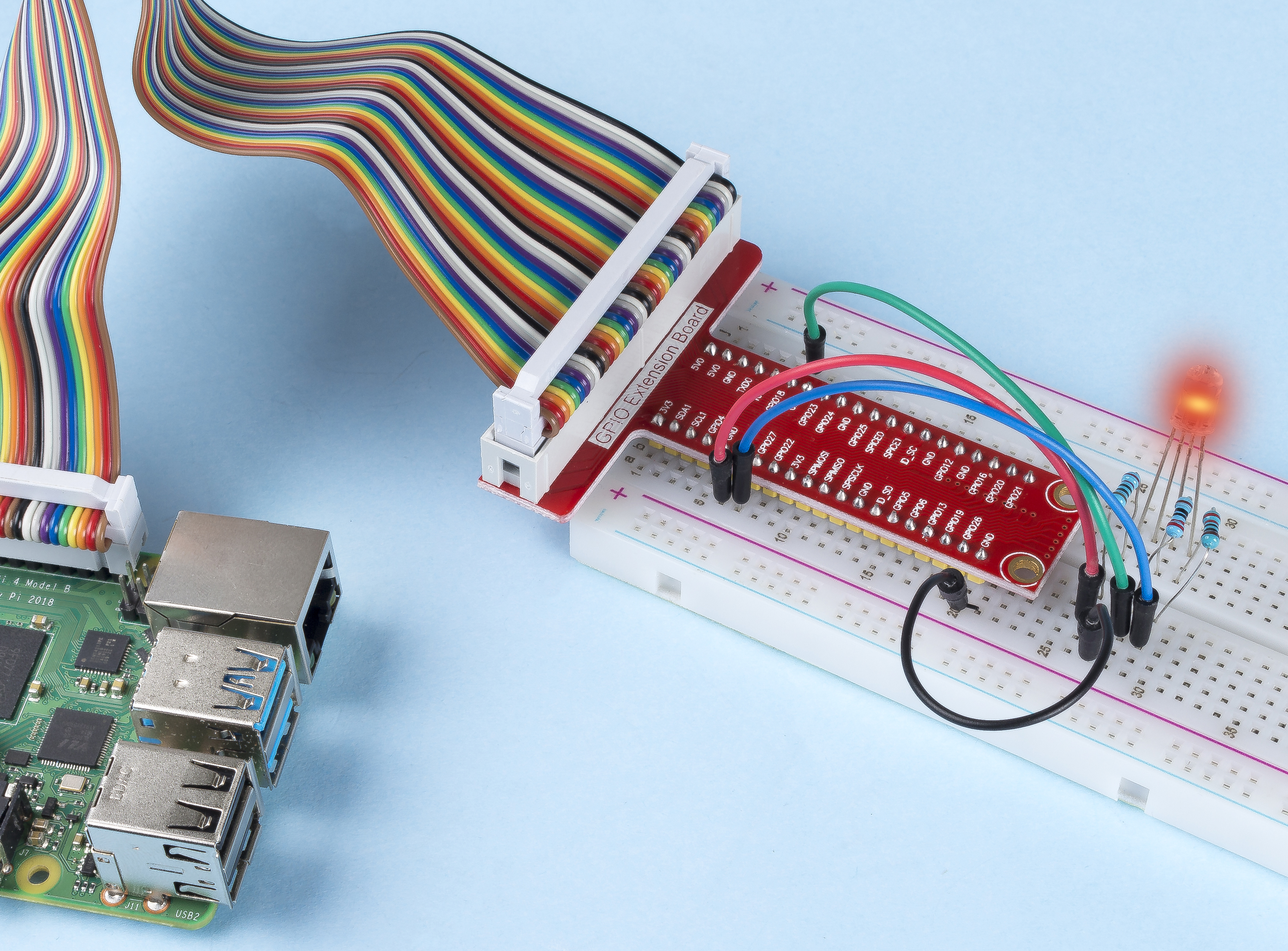
Phenomenon Picture