Note
Hello, welcome to the SunFounder Raspberry Pi & Arduino & ESP32 Enthusiasts Community on Facebook! Dive deeper into Raspberry Pi, Arduino, and ESP32 with fellow enthusiasts.
Why Join?
Expert Support: Solve post-sale issues and technical challenges with help from our community and team.
Learn & Share: Exchange tips and tutorials to enhance your skills.
Exclusive Previews: Get early access to new product announcements and sneak peeks.
Special Discounts: Enjoy exclusive discounts on our newest products.
Festive Promotions and Giveaways: Take part in giveaways and holiday promotions.
👉 Ready to explore and create with us? Click [here] and join today!
2.2.1 Photoresistor(MCP3008)
Note
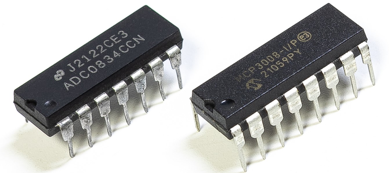
Depending on your kit version, please identify whether you have ADC0834 or MCP3008 and proceed with the matching section.
Introduction
Photoresistor is a commonly used component of ambient light intensity in life. It helps the controller to recognize day and night and realize light control functions such as night lamp. This project is very similar to potentiometer, and you might think it changing the voltage to sensing light.
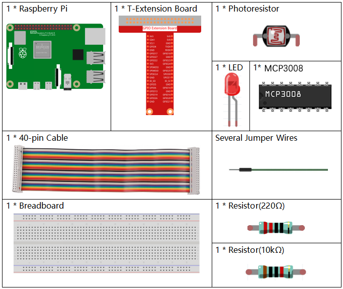
Required Components
In this project, we need the following components.
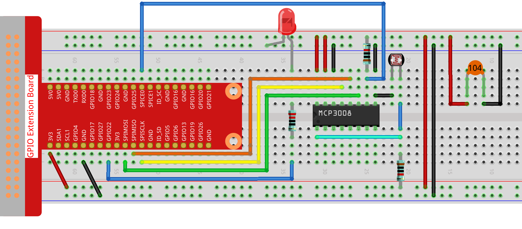
Schematic Diagram
T-Board Name |
physical |
WiringPi |
BCM |
|---|---|---|---|
SPICE0 |
pin24 |
10 |
8 |
SPIMOSI |
pin19 |
12 |
10 |
SPIMISO |
pin21 |
13 |
9 |
SPISCLK |
pin23 |
14 |
11 |
GPIO22 |
pin15 |
3 |
22 |

Experimental Procedures
Step 1: Build the circuit.
Step 2: Go to the folder of the code.
cd ~/davinci-kit-for-raspberry-pi/nodejs/
Step 3: Run the code.
sudo node photoresistor-2.js
Code
const Gpio = require('pigpio').Gpio;
const mcpadc = require('mcp-spi-adc');

// Open MCP3008 channel 0 (analog input CH0)
const adc = mcpadc.openMcp3008(0, { speedHz: 1350000 }, (err) => {
if (err) {
    console.error("Failed to open MCP3008:", err);
    process.exit(1);
}

console.log("MCP3008 initialized on SPI0/CE0.");

// Initialize LED on GPIO22 (PWM capable)
const led = new Gpio(22, { mode: Gpio.OUTPUT });

// Set up interval to read ADC and update LED brightness every 100ms
const interval = setInterval(() => {
    adc.read((err, reading) => {
    if (err) {
        console.error("ADC read error:", err);
        return;
    }

    const adcValue = reading.value;          // Float between 0.0 and 1.0
    const pwmValue = Math.round(adcValue * 255); // Scale to 0–255

    console.log(`ADC = ${adcValue.toFixed(4)}, PWM = ${pwmValue}`);

    led.pwmWrite(pwmValue); // Update LED brightness
    });
}, 100);

// Handle Ctrl+C (SIGINT) to clean up
process.on('SIGINT', () => {
    console.log('\nGracefully shutting down...');
    clearInterval(interval);  // Stop the interval loop
    led.digitalWrite(0);      // Turn off LED
    process.exit(0);
});
});
Code Explanation
const Gpio = require('pigpio').Gpio;
This line imports the pigpio module, which is used to control GPIO pins on the Raspberry Pi. It supports PWM output required for dimming an LED.
const mcpadc = require('mcp-spi-adc');
This line imports the mcp-spi-adc library, which enables communication with the MCP3008 analog-to-digital converter using the Raspberry Pi’s hardware SPI interface.
const adc = mcpadc.openMcp3008(0, { speedHz: 1350000 }, (err) => { ... });
Opens analog input channel 0 of the MCP3008 chip using hardware SPI. The SPI clock speed is set to 1.35 MHz. If an error occurs while opening the channel, the program logs it and exits.
const led = new Gpio(22, { mode: Gpio.OUTPUT });
Initializes GPIO pin 22 as an output. This pin is used to control the brightness of an LED using PWM via the pigpio library.
setInterval(() => {
    adc.read((err, reading) => {
        ...
    });
}, 100);
Sets up a recurring loop that runs every 100 milliseconds. Within each cycle, it reads the analog value from MCP3008 channel 0. The result is a floating-point number between 0.0 and 1.0, representing the ratio of input voltage to reference voltage.
const pwmValue = Math.round(adcValue * 255);
led.pwmWrite(pwmValue);
Converts the analog value to an 8-bit PWM value in the range 0–255, then writes it to GPIO22 to adjust LED brightness proportionally.
process.on('SIGINT', () => {
    clearInterval(interval);
    led.digitalWrite(0);
    process.exit(0);
});
Adds a signal handler to gracefully shut down the program when Ctrl+C is pressed. It stops the interval loop, turns off the LED, and exits the program cleanly.