2.1.2 Slide Switch
Introduction
In this project, we will learn how to use a slide switch. Usually,the slide switch is soldered on PCB as a power switch, but here we need to insert it into the breadboard, thus it may not be tightened. And we use it on the breadboard to show its function.
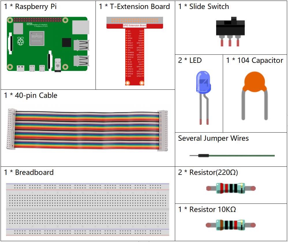
Components

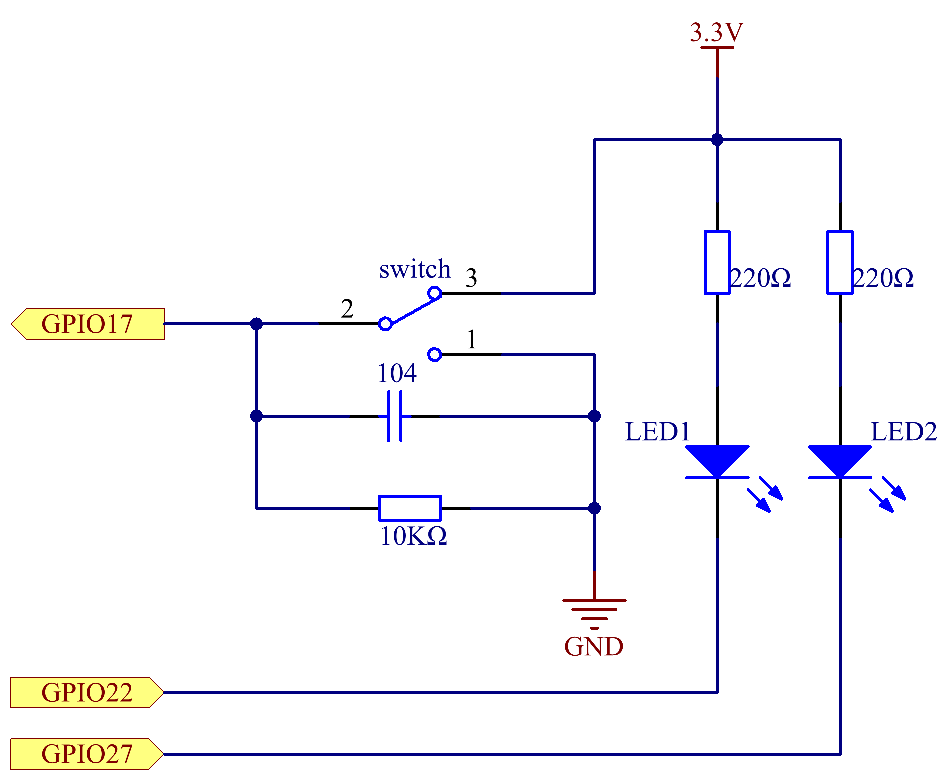
Schematic Diagram
Connect the middle pin of the Slide Switch to GPIO17, and two LEDs to pin GPIO22 and GPIO27 respectively. Then when you pull the slide, you can see the two LEDs light up alternately.


Experimental Procedures
Step 1: Build the circuit.

Step 2: Go to the folder of the code.
cd ~/davinci-kit-for-raspberry-pi/nodejs/
Step 3: Run the code.
sudo node slide_switch.js
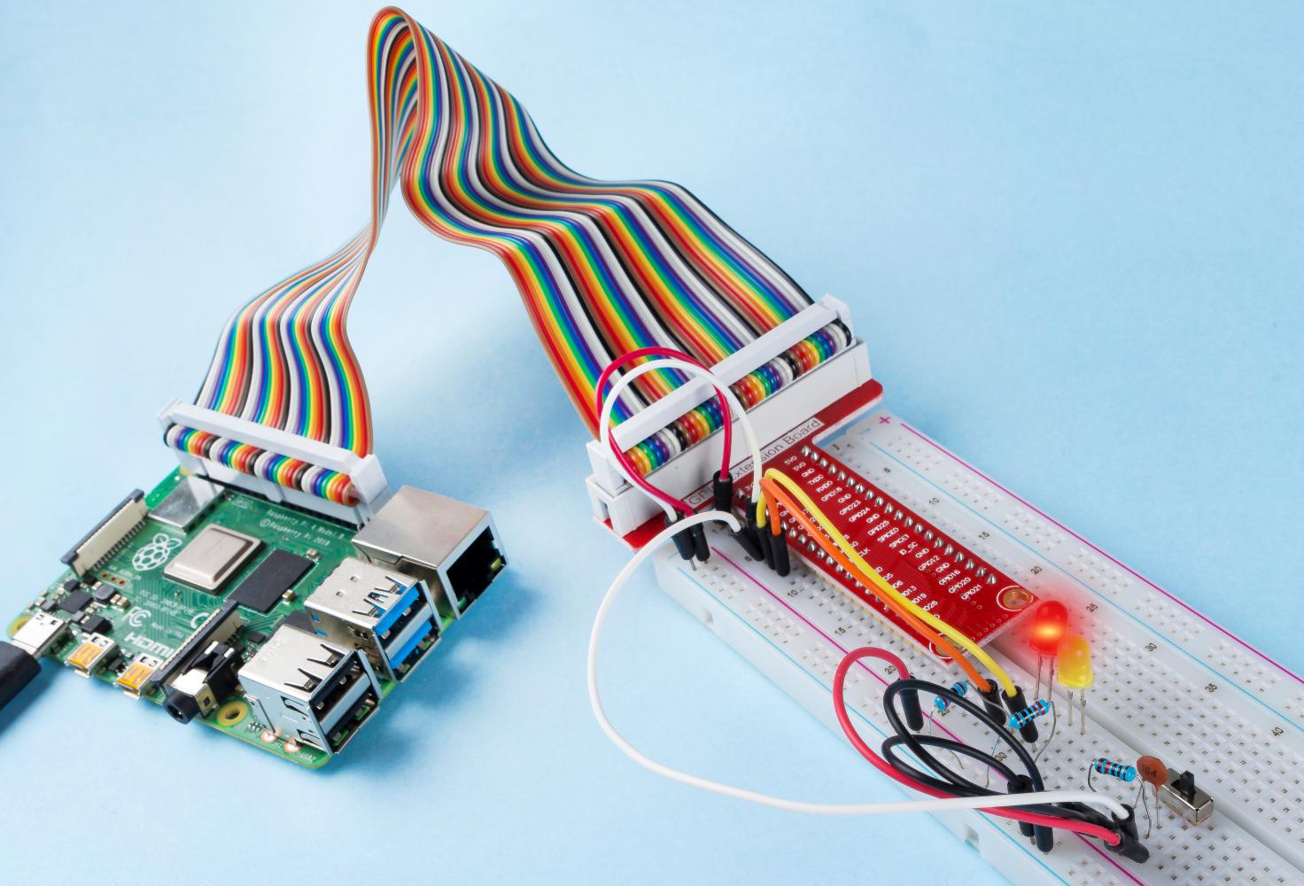
While the code is running, get the switch connected to the left, then the yellow LED lights up; to the right, the red light turns on.
Code
const Gpio = require('pigpio').Gpio;

const led1 = new Gpio(22, {mode: Gpio.OUTPUT});
const led2 = new Gpio(27, {mode: Gpio.OUTPUT});

const slideSwitch = new Gpio(17, {
    mode: Gpio.INPUT,
    pullUpDown: Gpio.PUD_DOWN,
    edge: Gpio.EITHER_EDGE
});

slideSwitch.on('interrupt', (level) => {
    led1.digitalWrite(level);
    led2.digitalWrite(!level);
});
Code Explanation
const Gpio = require('pigpio').Gpio;

const led1 = new Gpio(22, {mode: Gpio.OUTPUT});
const led2 = new Gpio(27, {mode: Gpio.OUTPUT});

const slideSwitch = new Gpio(17, {
    mode: Gpio.INPUT,
    pullUpDown: Gpio.PUD_DOWN,
    edge: Gpio.EITHER_EDGE
});
Import the pigpio module, and create three objects led1, led2, slideSwitch, and control the on and off of led1 and led2 by reading the level of the slideSwitch IO port.
slideSwitch.on('interrupt', (level) => {
    led1.digitalWrite(level);
    led2.digitalWrite(!level);
});
When the read level of the slideSwitch IO port changes, Write the same level to led1 and the opposite level to led2.
Phenomenon Picture
