Note
Hello, welcome to the SunFounder Raspberry Pi & Arduino & ESP32 Enthusiasts Community on Facebook! Dive deeper into Raspberry Pi, Arduino, and ESP32 with fellow enthusiasts.
Why Join?
Expert Support: Solve post-sale issues and technical challenges with help from our community and team.
Learn & Share: Exchange tips and tutorials to enhance your skills.
Exclusive Previews: Get early access to new product announcements and sneak peeks.
Special Discounts: Enjoy exclusive discounts on our newest products.
Festive Promotions and Giveaways: Take part in giveaways and holiday promotions.
👉 Ready to explore and create with us? Click [here] and join today!
2.1.6 Joystick(MCP3008)
Introduction
In this project, We’re going to learn how joystick works. We manipulate the Joystick and display the results on the screen.
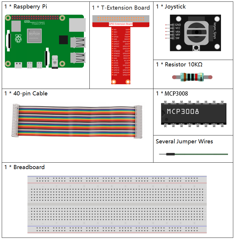
Required Components
In this project, we need the following components.
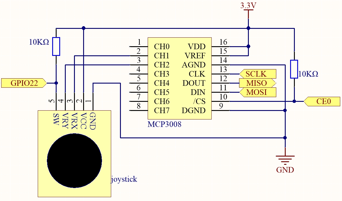
Schematic Diagram
When the data of joystick is read, there are some differents between axis: data of X and Y axis is analog, which need to use MCP3008 to convert the analog value to digital value. Data of Z axis is digital, so you can directly use the GPIO to read, or you can also use ADC to read.
Experimental Procedures
Step 1: Build the circuit.

Step 2: Go to the folder of the code.
cd ~/davinci-kit-for-raspberry-pi/nodejs/
Step 3: Run the code.
sudo node joystick-2.js
After the code runs, turn the Joystick, then the corresponding values of x, y, Btn are displayed on screen.
Code
const Gpio = require('pigpio').Gpio;
const mcpadc = require('mcp-spi-adc');

// Open channel 1 (X-axis)
const xChannel = mcpadc.openMcp3008(1, { speedHz: 1350000 }, (err) => {
if (err) {
    console.error('Failed to open X channel:', err);
    process.exit(1);
}
});

// Open channel 2 (Y-axis)
const yChannel = mcpadc.openMcp3008(2, { speedHz: 1350000 }, (err) => {
if (err) {
    console.error('Failed to open Y channel:', err);
    process.exit(1);
}
});

// Button input on GPIO22 with pull-up
const btn = new Gpio(22, {
mode: Gpio.INPUT,
pullUpDown: Gpio.PUD_UP,
});

// Read loop
setInterval(() => {
xChannel.read((errX, xReading) => {
    if (errX) {
    console.error('X channel read error:', errX);
    return;
    }

    yChannel.read((errY, yReading) => {
    if (errY) {
        console.error('Y channel read error:', errY);
        return;
    }

    const x_val = Math.round(xReading.value * 1023);
    const y_val = Math.round(yReading.value * 1023);
    const btn_val = btn.digitalRead();

    console.log(`x = ${x_val}, y = ${y_val}, btn = ${btn_val}\n`);
    });
});
}, 100);
Code Explanation
const mcpadc = require('mcp-spi-adc');
This line imports the mcp-spi-adc module, which allows communication with the MCP3008 ADC using the Raspberry Pi’s hardware SPI interface.
const xChannel = mcpadc.openMcp3008(1, { speedHz: 1350000 }, ...);
const yChannel = mcpadc.openMcp3008(2, { speedHz: 1350000 }, ...);
These lines open MCP3008 analog input channels 1 and 2 for reading joystick X and Y axis signals, respectively. The SPI communication speed is set to 1.35 MHz.
const btn = new Gpio(22, {
  mode: Gpio.INPUT,
  pullUpDown: Gpio.PUD_UP,
});
Initializes GPIO pin 22 as a digital input with an internal pull-up resistor enabled. This pin is used to read the state of a push button.
setInterval(() => {
  xChannel.read(...);
  yChannel.read(...);
}, 100);
This function runs every 100 milliseconds. It reads the joystick’s X and Y axis values via MCP3008 channels 1 and 2 using SPI. The floating-point values (range 0.0–1.0) are converted to 10-bit integers (0–1023). It also reads the button state using digitalRead() on GPIO22, returning 0 when pressed and 1 when released. All values are printed to the console.