Note
Hello, welcome to the SunFounder Raspberry Pi & Arduino & ESP32 Enthusiasts Community on Facebook! Dive deeper into Raspberry Pi, Arduino, and ESP32 with fellow enthusiasts.
Why Join?
Expert Support: Solve post-sale issues and technical challenges with help from our community and team.
Learn & Share: Exchange tips and tutorials to enhance your skills.
Exclusive Previews: Get early access to new product announcements and sneak peeks.
Special Discounts: Enjoy exclusive discounts on our newest products.
Festive Promotions and Giveaways: Take part in giveaways and holiday promotions.
👉 Ready to explore and create with us? Click [here] and join today!
LED Matrix Module
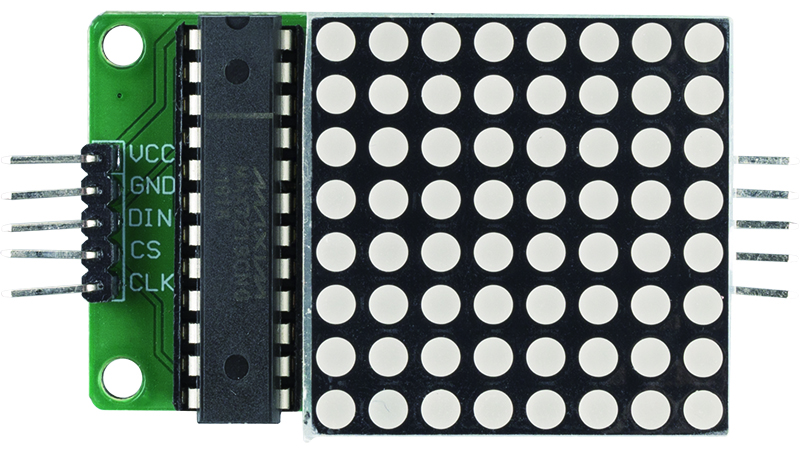
This is a common cathode 8x8 dot matrix module driven by MAX7219, the module operating voltage is 5V, the size is 50mmx32mmx15mm, the left side is input port, the right side is output port, support multiple modules cascade.
VCC: Positive Supply Voltage. Connect to +5V.
GND: Ground (both GND pins must be connected)
DIN: Serial-Data Input. Data is loaded into the internal 16-bit shift register on CLK’s rising edge.
CS: Chip-Select Input. Serial data is loaded into the shift register while CS is low. The last 16 bits of serial data are latched on CS’s rising edge.
CLK: Serial-Clock Input. 10MHz maximum rate. On CLK’s rising edge, data is shifted into the internal shift register. On CLK’s falling edge, data is clocked out of DOUT. On the MAX7221, the CLK input is active only while CS is low.
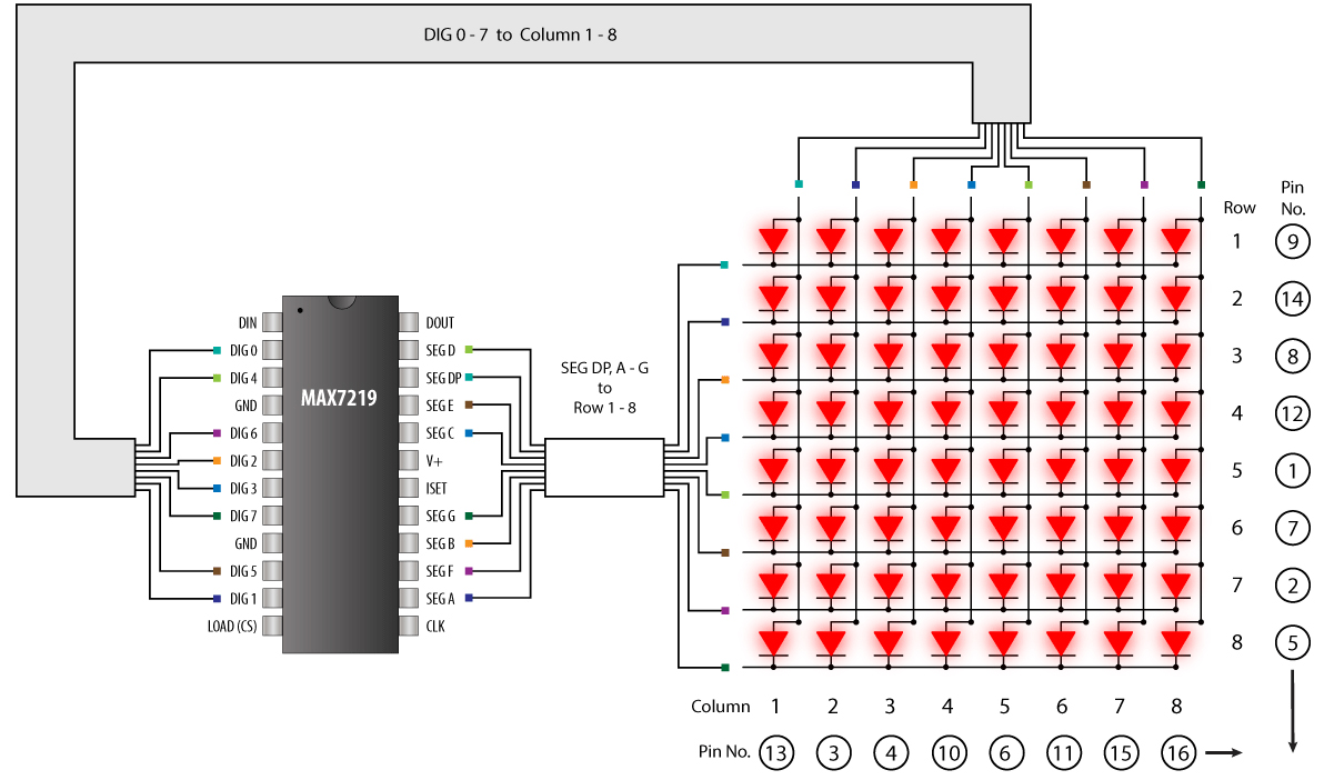
MAX7219
The MAX7219 is a compact, serial input/output common-cathode display drivers that interface microprocessors (µPs) to 7-segment numeric LED displays of up to 8 digits, bar-graph displays, or 64 individual LEDs. Included on-chip are a BCD code-B decoder, multiplex scan circuitry, segment and digit drivers, and an 8x8 static RAM that stores each digit.
Only one external resistor is required to set the segment current for all LEDs. The MAX7221 is compatible with SPI™, QSPI™, and MICROWIRE™, and has slewrate-limited segment drivers to reduce EMI.
A convenient 4-wire serial interface connects to all common µPs. Individual digits may be addressed and updated without rewriting the entire display. The MAX7219/MAX7221 also allow the user to select codeB decoding or no-decode for each digit.
Example
2.8 LED Matrix Module (Arduino Project)