Note
Hello, welcome to the SunFounder Raspberry Pi & Arduino & ESP32 Enthusiasts Community on Facebook! Dive deeper into Raspberry Pi, Arduino, and ESP32 with fellow enthusiasts.
Why Join?
Expert Support: Solve post-sale issues and technical challenges with help from our community and team.
Learn & Share: Exchange tips and tutorials to enhance your skills.
Exclusive Previews: Get early access to new product announcements and sneak peeks.
Special Discounts: Enjoy exclusive discounts on our newest products.
Festive Promotions and Giveaways: Take part in giveaways and holiday promotions.
👉 Ready to explore and create with us? Click [here] and join today!
Relay Module
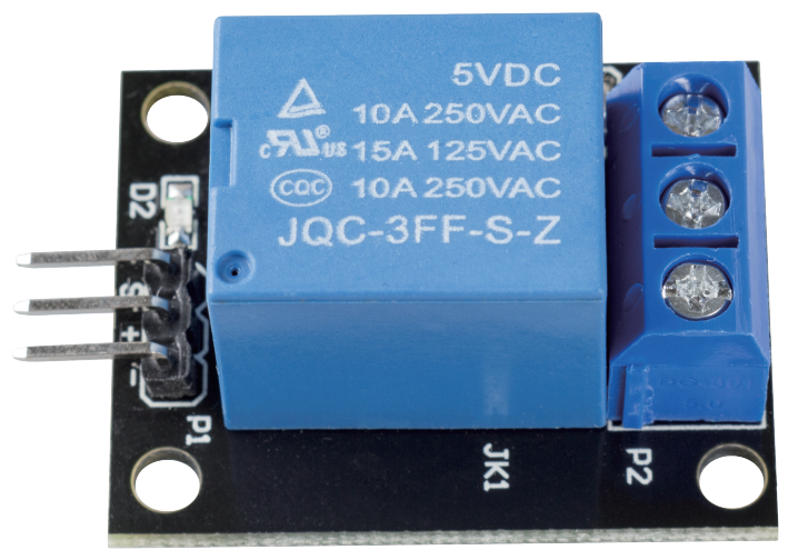
The relay module is a module consisting of a relay and a simple circuit that can be used to control large voltage devices, such as household appliances, by outputting a low voltage such as 3.3V from the control board.
FEATURES
Output: 250VAC-10A, 125VAC-10A, 30VDC-10A, 28VDC-10A.
Operating voltage 5V, suction current about 70mA.
With signal indicator
Input high and the relay closes, input low and the relay opens.
Using 8050 transistor to drive the relay action
With mounting screw holes
PCB size: 1.8cm*4.0cm*1.9cm, weight 15g
PINS OUT
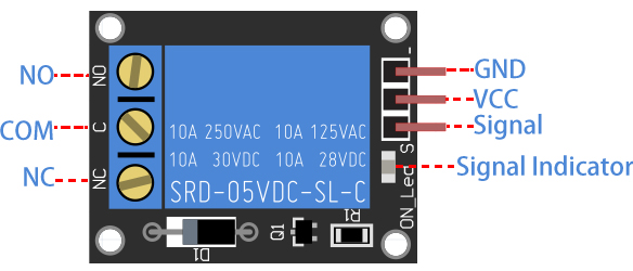
INPUT
It has a 1×3 (2.54mm pitch) pin header for connecting power (5V and 0V), and for controlling the relay. The pins are marked on the PCB:
-: GND
+: VCC
S: Signal pin, used to control this relay. Input high and the relay closes, input low and the relay opens.
OUTPUT
The 1 channel relay module could be considered like a series switches: 1 normally Open (NO), 1 normally closed (NC) and 1 common Pins (COM).
COM - Common pin
NC - Normally Closed, in which case NC is connected with COM when pin S is set low and disconnected when pin S is high.
NO - Normally Open, in which case NO is disconnected with COM when pin S is set low and connected when pin S is high.
HOW RELAY WORKS?
As we may know, relay is a device which is used to provide connection between two or more points or devices in response to the input signal applied. In other words, relays provide isolation between the controller and the device as devices may work on AC as well as on DC. However, they receive signals from a microcontroller which works on DC hence requiring a relay to bridge the gap. Relay is extremely useful when you need to control a large amount of current or voltage with small electrical signal.
There are 5 parts in every relay:
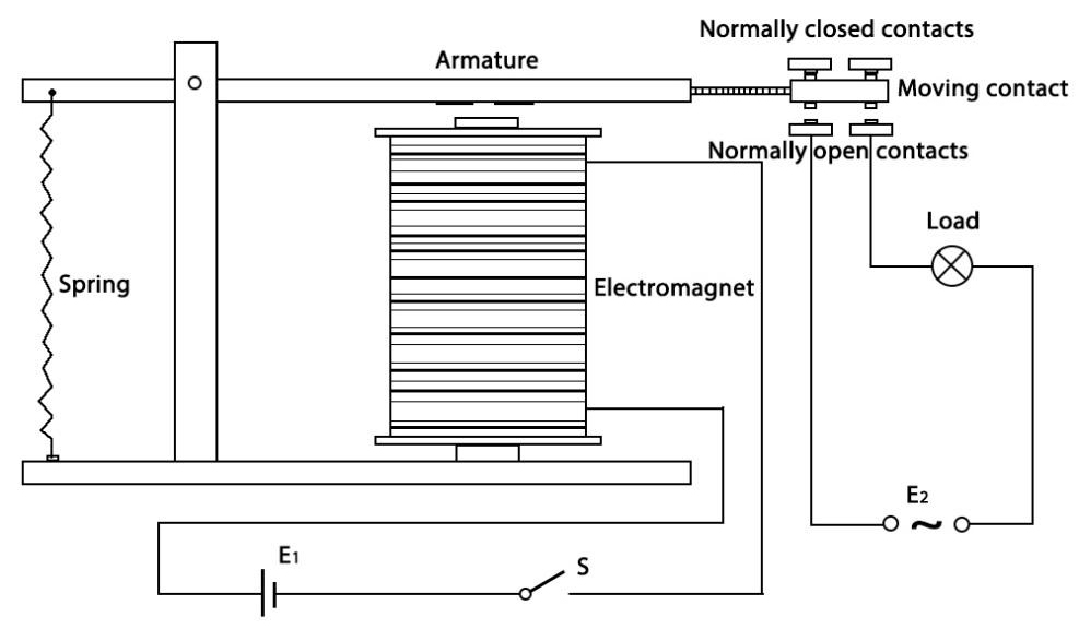
Electromagnet - It consists of an iron core wounded by coil of wires. When electricity is passed through, it becomes magnetic. Therefore, it is called electromagnet.
Armature - The movable magnetic strip is known as armature. When current flows through them, the coil is it energized thus producing a magnetic field which is used to make or break the normally open (N/O) or normally close (N/C) points. And the armature can be moved with direct current (DC) as well as alternating current (AC).
Spring - When no currents flow through the coil on the electromagnet, the spring pulls the armature away so the circuit cannot be completed.
Set of electrical contacts - There are two contact points:
Normally open - connected when the relay is activated, and disconnected when it is inactive.
Normally close - not connected when the relay is activated, and connected when it is inactive.
Molded frame - Relays are covered with plastic for protection.
The working principle of relay is simple. When power is supplied to the relay, currents start flowing through the control coil; as a result, the electromagnet starts energizing. Then the armature is attracted to the coil, pulling down the moving contact together thus connecting with the normally open contacts. So the circuit with the load is energized. Then breaking the circuit would a similar case, as the moving contact will be pulled up to the normally closed contacts under the force of the spring. In this way, the switching on and off of the relay can control the state of a load circuit.
Example
2.21 Relay Module (Arduino Project)
3.3 Overheat Monitor (Arduino Project)