Note
Hello, welcome to the SunFounder Raspberry Pi & Arduino & ESP32 Enthusiasts Community on Facebook! Dive deeper into Raspberry Pi, Arduino, and ESP32 with fellow enthusiasts.
Why Join?
Expert Support: Solve post-sale issues and technical challenges with help from our community and team.
Learn & Share: Exchange tips and tutorials to enhance your skills.
Exclusive Previews: Get early access to new product announcements and sneak peeks.
Special Discounts: Enjoy exclusive discounts on our newest products.
Festive Promotions and Giveaways: Take part in giveaways and holiday promotions.
👉 Ready to explore and create with us? Click [here] and join today!
Lesson 10 Servo
Introduction
Servo is a type of geared motor that can only rotate 180 degrees. It is controlled by sending electrical pulses from your board. These pulses tell the servo what position it should move to.
A servo has three wires: the brown wire is GND, the red one is VCC, and the orange one is signal line.
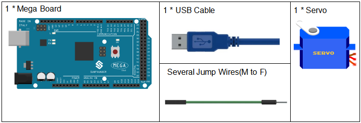
Components
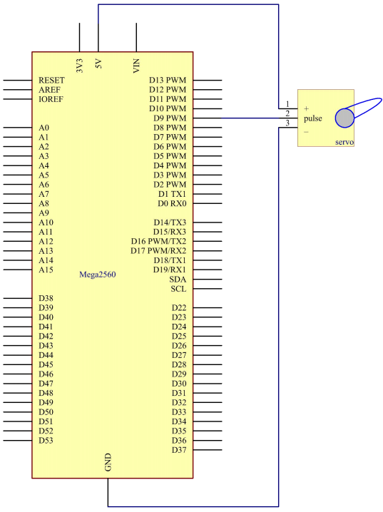
Schematic Diagram
The schematic diagram:
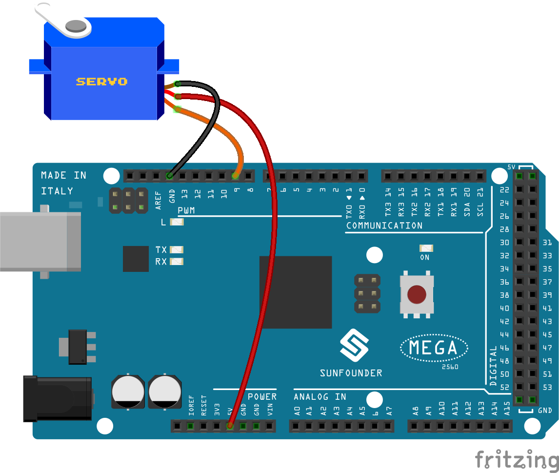
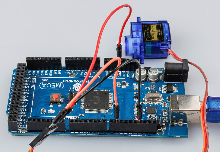
Experimental Procedures
Step 1: Build the circuit (Brown to GND, Red to VCC, Orange to pin 9 of the control board)
Step 2: Open the code file.
Step 3: Select the Board and Port.
Step 4: Upload the sketch to the board.
Now, you can see the rocker arm of the servo rotate and stop at 90 degrees (15 degrees each time). And then it rotates in the opposite direction.
Code
Code Analysis
Include a library
#include <Servo.h>

Servo myservo; //create servo object to control a servo
With the Servo.h file included, you can call the functions in this
file later. Servo is a built-in library in the Arduino IDE. You can find
the Servo folder under the installation path C:Program
FilesArduinolibraries.
Initialize the servo
void setup()

{

    myservo.attach(9); //attachs the servo on pin 9 to servo object

    myservo.write(0); //back to 0 degrees

    delay(1000); //wait for a second

}
myservo.attach(): Attach the Servo variable to a pin. Initialize the servo attach to pin9.
myservo.write(): Writes a value to the servo, controlling the shaft accordingly. On a standard servo, this will set the angle of the shaft (in degrees), moving the shaft to that orientation. Here let the servo stay in the 0 angle firstly.
Servo rotate
void loop()

{

    for (int i = 0; i <= 180; i++)

    {

        myservo.write(i); //write the i angle to the servo

        delay(15); //delay 15ms

    }

    for (int i = 180; i >= 0; i--)

    {

        myservo.write(i); //write the i angle to the servo

        delay(15); //delay 15ms

    }

}
Use 2 for() statement to write 0 - 180 to the servo, so that you can see the servo rotate from 0 to 180 angle,then turn back to 0.