Note
Hello, welcome to the SunFounder Raspberry Pi & Arduino & ESP32 Enthusiasts Community on Facebook! Dive deeper into Raspberry Pi, Arduino, and ESP32 with fellow enthusiasts.
Why Join?
Expert Support: Solve post-sale issues and technical challenges with help from our community and team.
Learn & Share: Exchange tips and tutorials to enhance your skills.
Exclusive Previews: Get early access to new product announcements and sneak peeks.
Special Discounts: Enjoy exclusive discounts on our newest products.
Festive Promotions and Giveaways: Take part in giveaways and holiday promotions.
👉 Ready to explore and create with us? Click [here] and join today!
Lesson 17 7-Segment Display
Introduction
A 7-segment display is a device that can display numerals and letters. It’s made up of seven LEDs connected in parallel. Different letters/numbers can be shown by connecting pins on the display to the power source and enabling the related pins, thus turning on the corresponding LED segments. In this lesson let’s learn how to display specific characters on it.
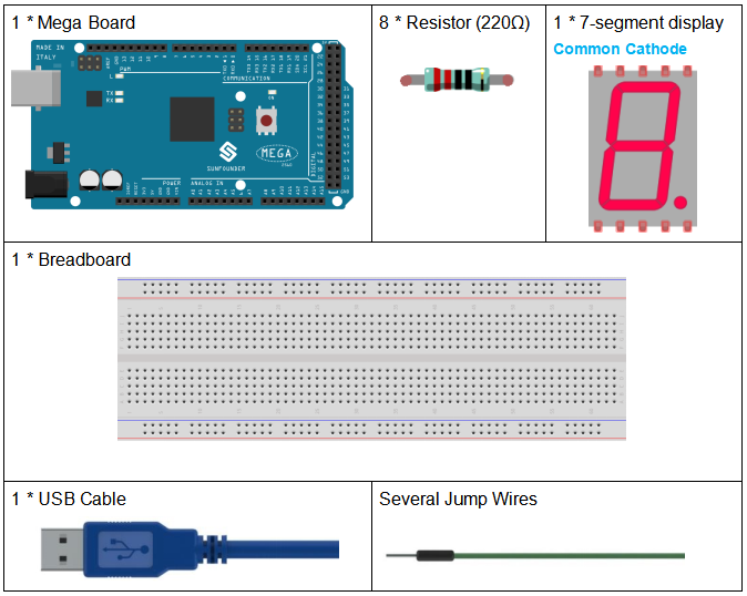
Components
Schematic Diagram
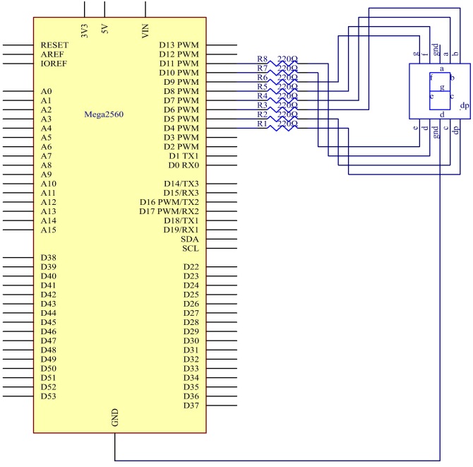
In this experiment, connect each of pin a-g of the 7-Segment Display to one 220ohm current limiting resistor respectively and then to pin 4-11. GND connects to GND. By programming, we can set one or several of pin4-11 as High level to light up the corresponding LED(s).
The schematic diagram:
Experimental Procedures
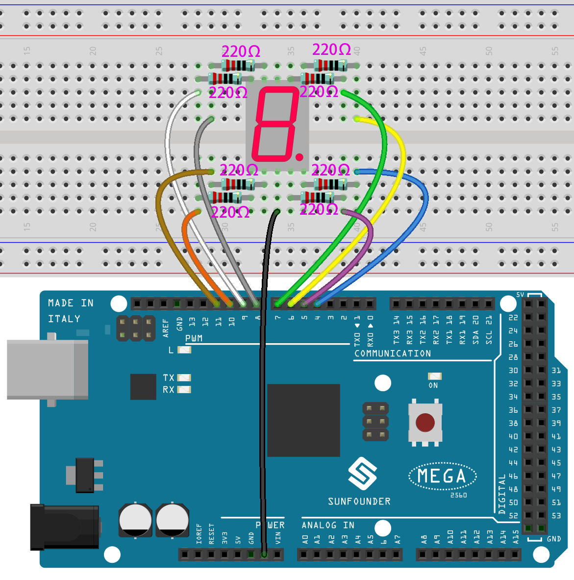
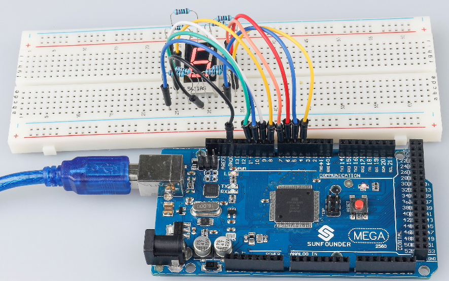
Step 1: Build the circuit (here a common cathode 7-segment display is used)
The wiring between the 7-segment display and the Mega2560 board :
7-Segment |
Mega2560 Board |
a |
7 |
b |
6 |
c |
5 |
d |
11 |
e |
10 |
f |
8 |
g |
9 |
dp |
4 |
“ - “ |
GND |
Step 2: Open the code file.
Step 3: Select the Board and Port.
Step 4: Upload the sketch to the board.
You should now see the 7-segment display from 0 to 9 and then A to F, back and forth.
Code
Code Analysis
The code may be a little long for this experiment. But the syntax is simple. Let’s take a look.
Call the function in loop()
digital_1(); //diaplay 1 to the 7-segment

delay(1000); //wait for a second

digital_2(); //diaplay 2 to the 7-segment

delay(1000); //wait for a second

digital_3(); //diaplay 3 to the 7-segment

delay(1000); //wait for a second

digital_4(); //diaplay 4 to the 7-segment
Calling these functions into the loop() is to let the 7-Segment display
0-F. The functions are shown below. Take digital_2() for example:
Detailed analysis of digital_2()
void digital_2(void) //diaplay 2 to the 7-segment

{

digitalWrite(b,HIGH);

digitalWrite(a,HIGH);

for(int j = 9;j <= 11;j++)

   digitalWrite(j,HIGH);

   digitalWrite(c,LOW);

   digitalWrite(f,LOW);

}
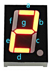
First we need to know how it looks like when display the numeral 2
on the 7-Segment display. It’s actually the segments a, b, d, e and g
are power on, which generates the display of 2. In programming, pins
connected to these segments are set High level when c and f are Low
level. Here we use a for() statement to set these pins as High level
respectively (the braces after for() are deleted as there is only one
line). Connect pin dp to pin 4; it’s already defined as LOW in
setup().
After running this part, the 7-segment will display 2. Similarly, the display of other characters are the same. Since the letters b and d in upper case, namely B and D, would look the same with 8 and 0 on the display, they are displayed in lower case instead.