Note
Hello, welcome to the SunFounder Raspberry Pi & Arduino & ESP32 Enthusiasts Community on Facebook! Dive deeper into Raspberry Pi, Arduino, and ESP32 with fellow enthusiasts.
Why Join?
Expert Support: Solve post-sale issues and technical challenges with help from our community and team.
Learn & Share: Exchange tips and tutorials to enhance your skills.
Exclusive Previews: Get early access to new product announcements and sneak peeks.
Special Discounts: Enjoy exclusive discounts on our newest products.
Festive Promotions and Giveaways: Take part in giveaways and holiday promotions.
👉 Ready to explore and create with us? Click [here] and join today!
Servo
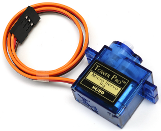
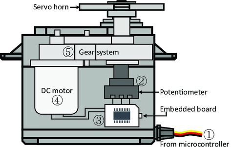
A servo is generally composed of the following parts: case, shaft, gear system, potentiometer, DC motor, and embedded board.
It works like this: The microcontroller sends out PWM signals to the servo, and then the embedded board in the servo receives the signals through the signal pin and controls the motor inside to turn. As a result, the motor drives the gear system and then motivates the shaft after deceleration. The shaft and potentiometer of the servo are connected together. When the shaft rotates, it drives the potentiometer, so the potentiometer outputs a voltage signal to the embedded board. Then the board determines the direction and speed of rotation based on the current position, so it can stop exactly at the right position as defined and hold there.
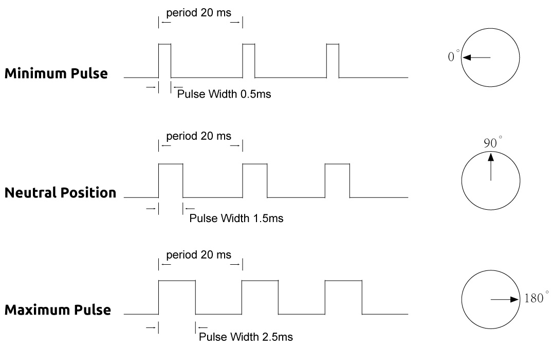
The angle is determined by the duration of a pulse that is applied to the control wire. This is called Pulse width Modulation. The servo expects to see a pulse every 20 ms. The length of the pulse will determine how far the motor turns. For example, a 1.5ms pulse will make the motor turn to the 90 degree position (neutral position). When a pulse is sent to a servo that is less than 1.5 ms, the servo rotates to a position and holds its output shaft some number of degrees counterclockwise from the neutral point. When the pulse is wider than 1.5 ms the opposite occurs. The minimal width and the maximum width of pulse that will command the servo to turn to a valid position are functions of each servo. Generally the minimum pulse will be about 0.5 ms wide and the maximum pulse will be 2.5 ms wide.
Example
Lesson 10 Servo (Mega Board Project)
Lesson 10 Servo (R3 Board Project)