Note
Hello, welcome to the SunFounder Raspberry Pi & Arduino & ESP32 Enthusiasts Community on Facebook! Dive deeper into Raspberry Pi, Arduino, and ESP32 with fellow enthusiasts.
Why Join?
Expert Support: Solve post-sale issues and technical challenges with help from our community and team.
Learn & Share: Exchange tips and tutorials to enhance your skills.
Exclusive Previews: Get early access to new product announcements and sneak peeks.
Special Discounts: Enjoy exclusive discounts on our newest products.
Festive Promotions and Giveaways: Take part in giveaways and holiday promotions.
👉 Ready to explore and create with us? Click [here] and join today!
Lesson 8 Controlling an LED by Potentiometer
Introduction
In this lesson, let’s see how to change the luminance of an LED by a potentiometer, and receive the data of the potentiometer in Serial Monitor to see its value change.
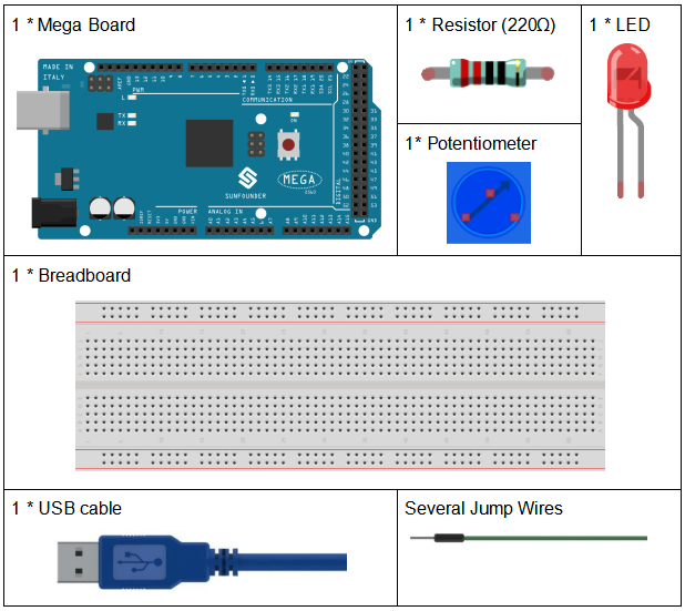
Components
Serial Monitor
Serial Monitor is used for communication between the Mega 2560 board and a computer or other devices. It is a built-in software in the Arduino environment and you can click the button on the upper right corner to open it. You can send and receive data via the serial port on the control board and control the board by input from the keyboard.
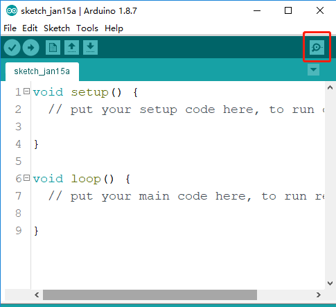
Here, the Serial Monitor serves as a transfer station for communication between your computer and the Mega 2560 board. First, the computer transfers data to the Serial Monitor, and then the data is read by the Mega 2560 board. Finally, the Mega 2560 will perform related operations. Click the icon at the top right corner and a window will pop up as shown below:

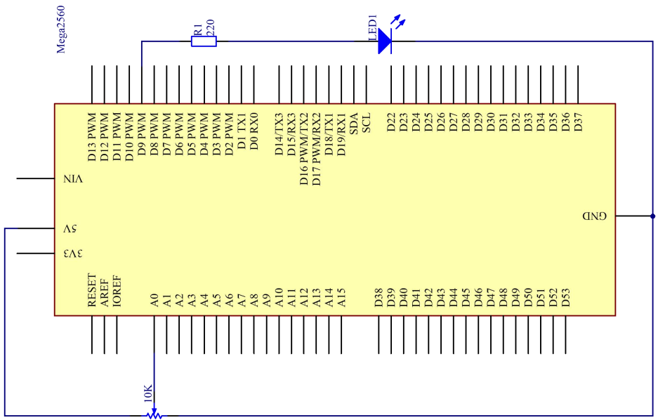
In this experiment, the potentiometer is used as voltage divider, meaning connecting devices to all of its three pins. Connect the middle pin of the potentiometer to pin A0 and the other two pins to 5V and GND respectively. Therefore, the voltage of the potentiometer is 0-5V. Spin the knob of the potentiometer, and the voltage at pin A0 will change. Then convert that voltage into a digital value (0-1024) with the AD converter in the control board. Through programming, we can use the converted digital value to control the brightness of the LED on the control board.
Schematic Diagram
Experimental Procedures
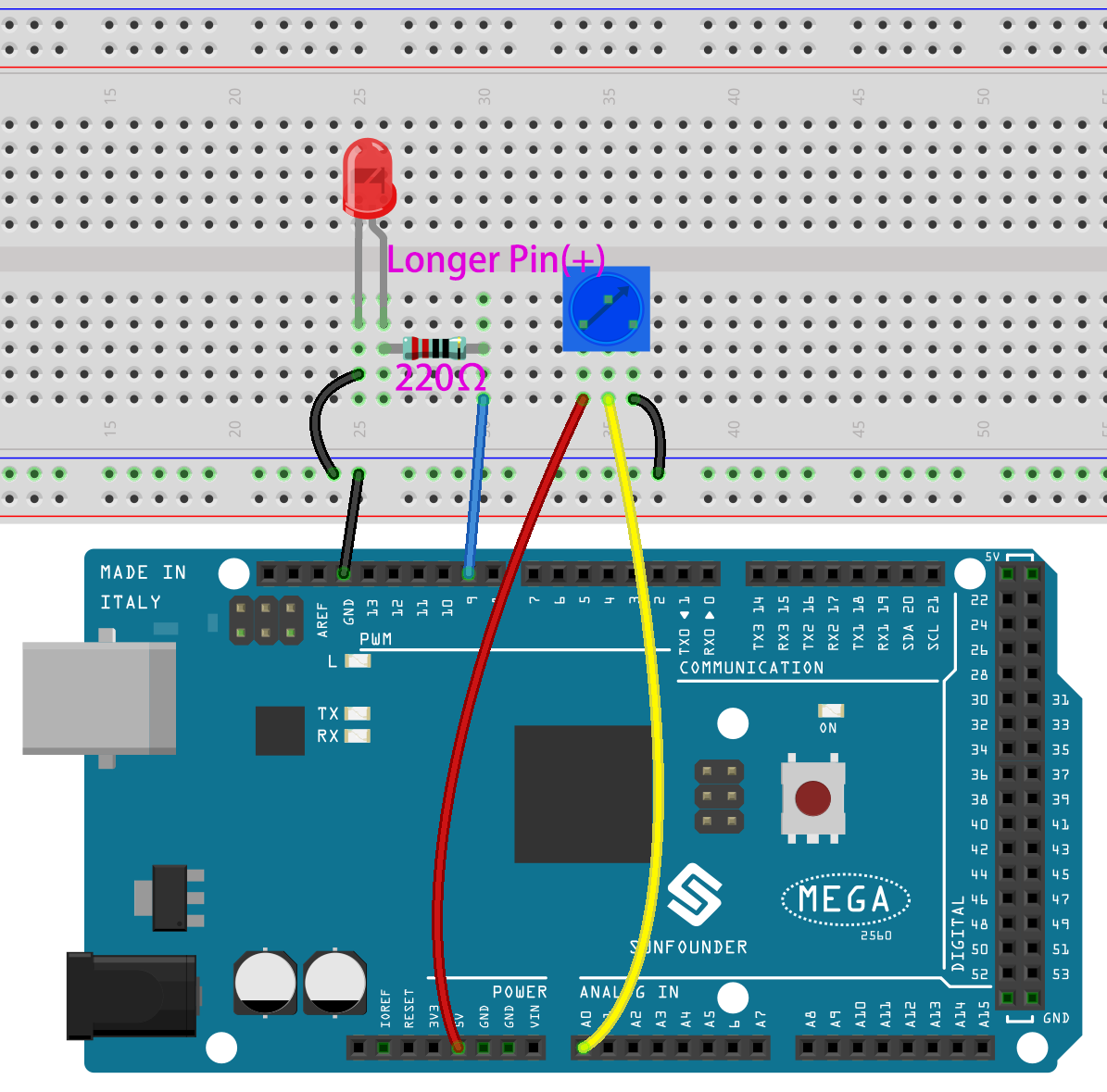
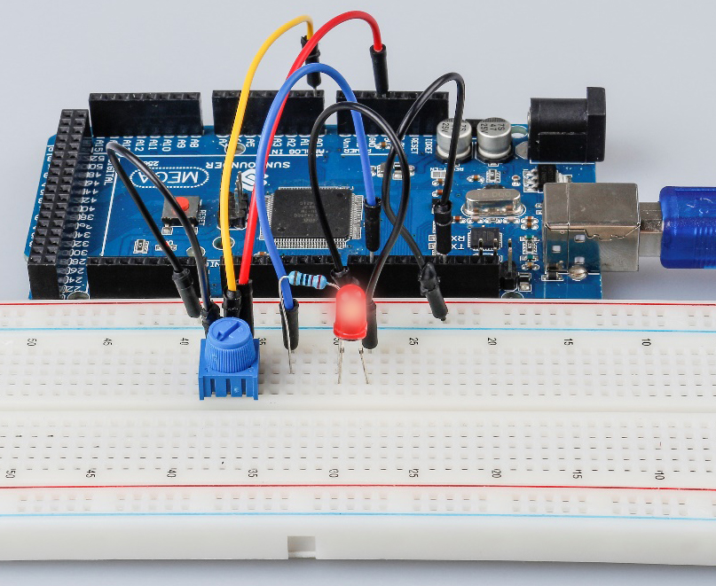
Step 1: Build the circuit
Step 2: Open the code file.
Step 3: Select the Board and Port.
Step 4: Upload the sketch to the board.
Step5: Open the Serial Monitor.
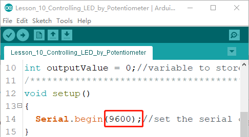
Find the Serial.begin() code to see what baud rate is set, here is 9600. Then click the top right corner icon to open the Serial Monitor.
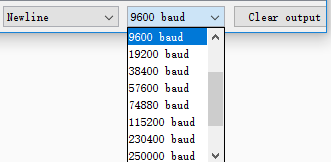
Step6: Set the baud rate to 9600.
The default baud rate for serial monitors is 9600, and if the code is also set to 9600, there is no need to change the baud rate bar.
Spin the shaft of the potentiometer and you should see the luminance of the LED change.
If you want to check the corresponding value changes, open the Serial Monitor and the data in the window will change with your spinning of the potentiometer knob.
Code
Code Analysis
Read the value from A0
inputValue = analogRead(analogPin);//read the value from the potentiometer
This line is to store the values A0 has read in the inputValue which
has been defined before.
analog Read() reads the value from the specified analog pin. This means that it will map input voltages between 0 and 5 volts into integer values between 0 and 1023.
Print values on Serial Monitor
Serial.print("Input: "); //print "Input"

Serial.println(inputValue); //print inputValue
Serial.print(): Prints data to the serial port as human-readable ASCII text. This command can take many forms. Numbers are printed using an ASCII character for each digit. Floats are similarly printed as ASCII digits, defaulting to two decimal places. Bytes are sent as a single character. Characters and strings are sent as is.Serial.println(): Takes the same forms as Serial.print(), but it is followed by a carriage return character (ASCII 13, or ‘\r’) and a newline character (ASCII 10, or ‘\n’).
Map the values
outputValue = map(inputValue, 0, 1023, 0, 255); //Convert from 0-1023 proportional to the number of a number of from 0 to 255
map(value, fromLow, fromHigh, toLow, toHigh) re-maps a number from
one range to another. That is, a value of Fromm would get mapped
to one of to Low, and a value of from High to one of thigh,
values in-between to values in-between, etc.
As the range of led Pin (pin 9) is 0-255, we need to map 0-1023 with
0-255.
Display the output value in Serial Monitor in the same way. If you are
not so clear about the map() functions, you can observe the data in
the Serial Monitor and analyze it.
Serial.print("Output: "); //print "Output"

Serial.println(outputValue); //print outputValue
Write the value of the potentiometer to LED
analogWrite(ledPin, outputValue); //turn the LED on depending on the output value
Write the output value to led Pin and you will see that the luminance
of LED changes with your spinning of the potentiometer knob.
analog Write(): Writes an analog value (PWM wave) to a pin. It has
nothing to do with an analog pin, but is just for PWM pins. You do not
need to call the incommode() to set the pin as output before calling
analog Write().
Experiment Summary
This experiment can also be changed to others as you like. For example, use the potentiometer to control the time interval for the LED blinking. It is to use the value read from the potentiometer for delaying, as shown below. Have a try!
inputValue = analogRead(analogPin);

digitalWrite(ledPin, HIGH);

delay(inputValue);

digitalWrite(ledPin, LOW);

delay(inputValue);