Note
Hello, welcome to the SunFounder Raspberry Pi & Arduino & ESP32 Enthusiasts Community on Facebook! Dive deeper into Raspberry Pi, Arduino, and ESP32 with fellow enthusiasts.
Why Join?
Expert Support: Solve post-sale issues and technical challenges with help from our community and team.
Learn & Share: Exchange tips and tutorials to enhance your skills.
Exclusive Previews: Get early access to new product announcements and sneak peeks.
Special Discounts: Enjoy exclusive discounts on our newest products.
Festive Promotions and Giveaways: Take part in giveaways and holiday promotions.
👉 Ready to explore and create with us? Click [here] and join today!
Lesson 7 RGB LED
Introduction
Previously we’ve used the digital pin to control an LED brighten and dim. In this lesson, we will use PWM to control an RGB LED to flash various kinds of color. When different PWM values are set to the R, G, and B pins of the LED, its brightness will be different. When the three different colors are mixed, we can see that the RGB LED flashes different colors.
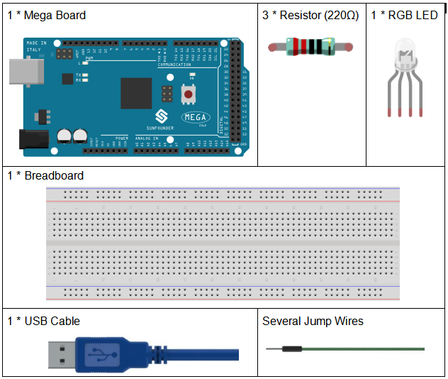
Components
PWM
Pulse width modulation, or PWM, is a technique for getting analog results with digital means. Digital control is used to create a square wave, a signal switched between on and off. This on-off pattern can simulate voltages in between full on (5 Volts) and off (0 Volts) by changing the portion of the time the signal spends on versus the time that the signal spends off. The duration of “on time” is called pulse width. To get varying analog values, you change, or modulate, that width. If you repeat this on-off pattern fast enough with some device, an LED for example, it would be like this: the signal is a steady voltage between 0 and 5V controlling the brightness of the LED. (See the PWM description on the official website of Arduino).
In the graphic below, the green lines represent a regular time period. This duration or period is the inverse of the PWM frequency. In other words, with Arduino’s PWM frequency at about 500Hz, the green lines would measure 2 milliseconds each.
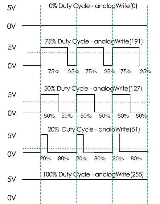
A call to analogWrite() is on a scale of 0 - 255, such that analogWrite(255) requests a 100% duty cycle (always on), and analogWrite(127) is a 50% duty cycle (on half the time) for example.
You will find that the smaller the PWM value is, the smaller the value will be after being converted into voltage. Then the LED becomes dimmer accordingly. Therefore, we can control the brightness of the LED by controlling the PWM value.
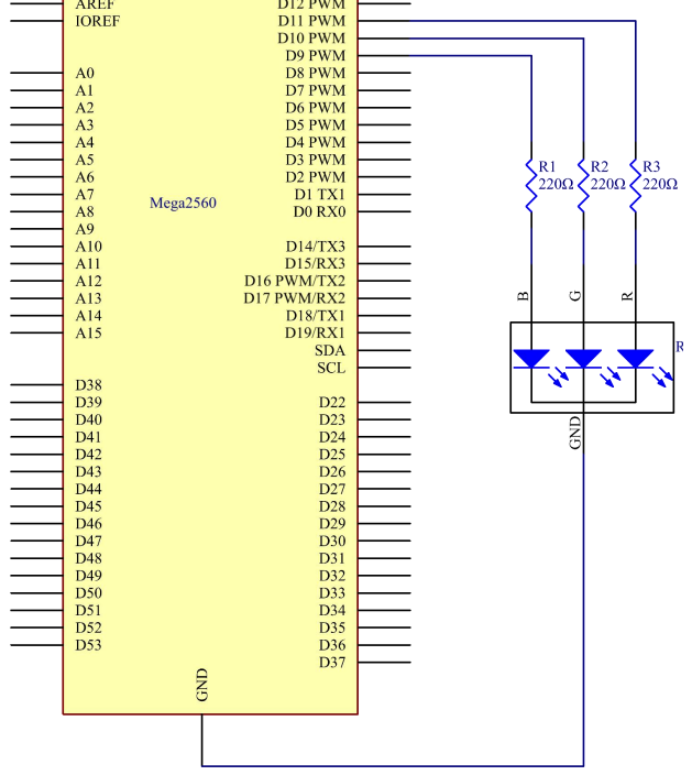
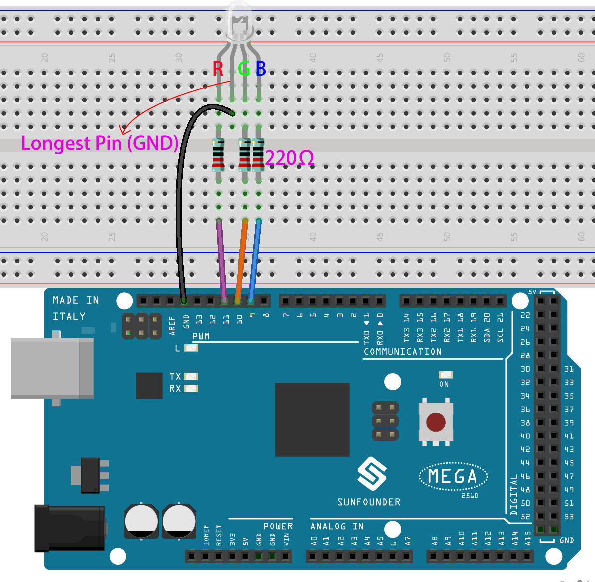
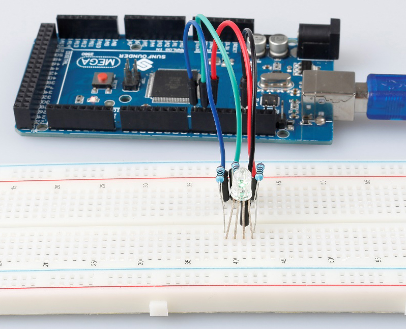
On the Mega2560 board, 2 to 13 and 44 to 46. Provide 8-bit PWM output with the analogWrite() function. You can connect any of these pins.Here we input a value between 0 and 255 to the three pins of the RGB LED to make it display different colors. After connecting the pins of R, G, and B to a current limiting resistor, connect them to the pin 9, pin 10, and pin 11 respectively. The longest pin (GND) of the LED connects to the GND of the Mega 2560. When the three pins are given different PWM values, the RGB LED will display different colors.
Schematic Diagram
Experimental Procedures
Step 1: Build the circuit
Step 2: Open the code file.
Step 3: Select the Board and Port.
Step 4: Upload the sketch to the board.
Here you should see the RGB LED flash circularly red, green, and blue first, then red, orange, yellow, green, blue, indigo, and purple.
Code
Code Analysis
Set the color
Here use the color() function to set the color of the RGB LED. In the
code, it is set to flash 7 different colors.
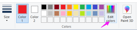
You can use the paint tool on your computer to get the RGB value.
Open the paint tool on your computer and click to Edit colors.
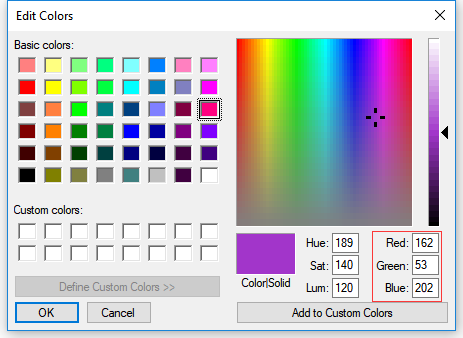
Select one color, then you can see the RGB value of this color. Fill them in the code.
void loop() // run over and over again

{

  // Basic colors:

  color(255, 0, 0); // turn the RGB LED red

  delay(1000); // delay for 1 second

  color(0,255, 0); // turn the RGB LED green

  delay(1000); // delay for 1 second

  color(0, 0, 255); // turn the RGB LED blue

  delay(1000); // delay for 1 second

  // Example blended colors:

  color(255,0,252); // turn the RGB LED red

  delay(1000); // delay for 1 second

  color(237,109,0); // turn the RGB LED orange

  delay(1000); // delay for 1 second

  color(255,215,0); // turn the RGB LED yellow

  ......
color()function
void color (unsigned char red, unsigned char green, unsigned char blue)
// the color generating function

{

  analogWrite(redPin, red);

  analogWrite(greenPin, green);

  analogWrite(bluePin, blue);

}
Define three unsigned char variables, red, green and blue. Write
their values to redPin, greenPin and bluePin. For example,
color(128,0,128) is to write 128 to redPin, 0 to greenPin and 128 to
bluePin. Then the result is the LED flashing purple.
analogWrite(): Writes an analog value (PWM wave) to a pin. It has
nothing to do with an analog pin, but is just for PWM pins. You do not
need to call the pinMode() to set the pin as output before calling
analogWrite().