Note
Hello, welcome to the SunFounder Raspberry Pi & Arduino & ESP32 Enthusiasts Community on Facebook! Dive deeper into Raspberry Pi, Arduino, and ESP32 with fellow enthusiasts.
Why Join?
Expert Support: Solve post-sale issues and technical challenges with help from our community and team.
Learn & Share: Exchange tips and tutorials to enhance your skills.
Exclusive Previews: Get early access to new product announcements and sneak peeks.
Special Discounts: Enjoy exclusive discounts on our newest products.
Festive Promotions and Giveaways: Take part in giveaways and holiday promotions.
👉 Ready to explore and create with us? Click [here] and join today!
Light-sensitive Array
This program converts the readings from a light-dependent resistor into a corresponding number of illuminated LED lights, creating a simple indicator of light brightness.
Required Components
In this project, we need the following components.
It’s definitely convenient to buy a whole kit, here’s the link:
Name |
ITEMS IN THIS KIT |
LINK |
|---|---|---|
Elite Explorer Kit |
300+ |
You can also buy them separately from the links below.
COMPONENT INTRODUCTION |
PURCHASE LINK |
|---|---|
- |
|
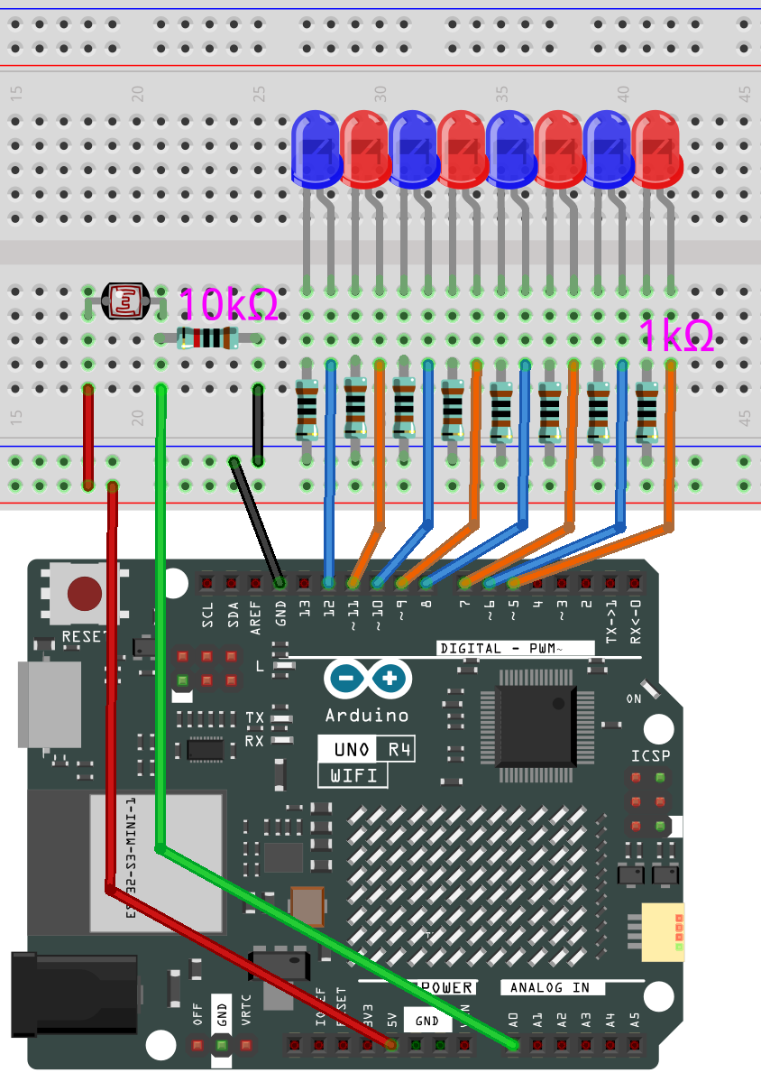
Wiring
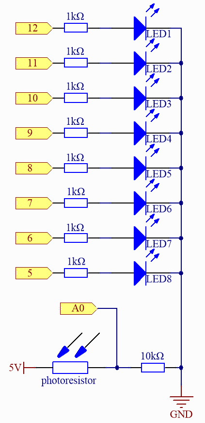
Schematic
Code
Note
You can open the file
04_light_sensitive_array.inounder the path ofelite-explorer-kit-main\fun_project\04_light_sensitive_arraydirectly.Or copy this code into Arduino IDE.
 1/*
 2  The code reads the ambient light level through a photoresistor and lights up
 3  a certain number of LEDs based on the light level. The LEDs serve as a "light level bar."
 4
 5  Board: Arduino Uno R4
 6  Component: Photoresistor and LED
 7*/
 8
 9// Constants for the number of LEDs and their pins
10const int NbrLEDs = 8;
11const int ledPins[] = { 5, 6, 7, 8, 9, 10, 11, 12 };
12
13// Pin for the photoresistor
14const int photocellPin = A0;
15
16// Variables to store sensor and LED level values
17int sensorValue = 0;  // value read from the sensor
18int ledLevel = 0;     // sensor value converted into LED 'bars'
19
20void setup() {
21  // Initialize all LED pins as outputs
22  for (int led = 0; led < NbrLEDs; led++) {
23    pinMode(ledPins[led], OUTPUT);
24  }
25}
26
27void loop() {
28  sensorValue = analogRead(photocellPin);              // Read the ambient light level from the photoresistor
29  ledLevel = map(sensorValue, 300, 1023, 0, NbrLEDs);  // Map the sensor value to the number of LEDs to be lit
30
31  // Update the state of each LED based on the mapped value
32  for (int led = 0; led < NbrLEDs; led++) {
33    if (led < ledLevel) {
34      digitalWrite(ledPins[led], HIGH);  // Turn ON LEDs that are below the level
35    } else {
36      digitalWrite(ledPins[led], LOW);  // Turn OFF LEDs that are above the level
37    }
38  }
39}
How it works?
Here’s a step-by-step explanation of the code:
Constant and Variable Definitions:
NbrLEDs: Defines the presence of 8 LEDs.ledPins[]: LEDs are connected to Arduino pins 5 to 12.photocellPin: The photoresistor is connected to Arduino’s A0 pin.sensorValue: This variable stores the value read from the photoresistor.ledLevel: This variable stores the number of LEDs based on the sensorValue conversion.setup():Configures pins 5 to 12 as output to drive the LEDs.
loop():Reads the analog value of the photoresistor from pin A0, typically ranging from 0 to 1023. Uses the map function to map the photoresistor’s value from the range 300-1023 to the range 0-8. This means that if the reading from the light-dependent resistor is 300, no LEDs will be lit; if the reading is 1023 or higher, all 8 LEDs will be lit.
The subsequent for loop checks each LED. If its index is less than ledLevel, the LED will be turned on; otherwise, it will be turned off.