Note
Hello, welcome to the SunFounder Raspberry Pi & Arduino & ESP32 Enthusiasts Community on Facebook! Dive deeper into Raspberry Pi, Arduino, and ESP32 with fellow enthusiasts.
Why Join?
Expert Support: Solve post-sale issues and technical challenges with help from our community and team.
Learn & Share: Exchange tips and tutorials to enhance your skills.
Exclusive Previews: Get early access to new product announcements and sneak peeks.
Special Discounts: Enjoy exclusive discounts on our newest products.
Festive Promotions and Giveaways: Take part in giveaways and holiday promotions.
👉 Ready to explore and create with us? Click [here] and join today!
Remote Relay Controller with Blynk
This project aims to create a remote relay controller that can be operated through a virtual switch in the Blynk app. When the switch is turned on, it sets the digital pin connected to the relay to HIGH, and when it’s turned off, it sets the digital pin to LOW. This allows for easy control of the relay from a distance, effectively creating a remote switch.
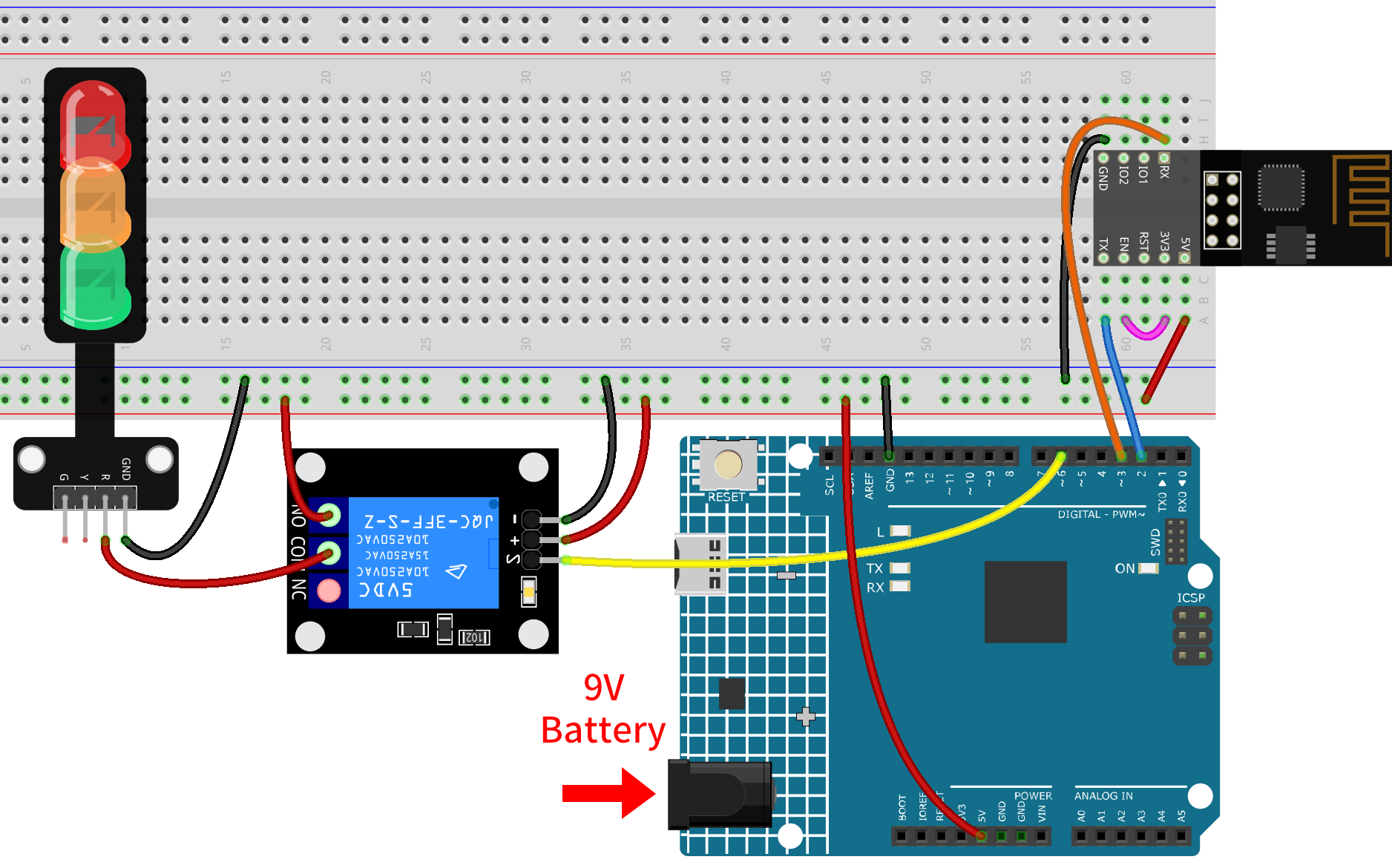
1. Build the Circuit
Warning
The following example demonstrates using a relay to control an LED module. While you can connect the relay to other appliances in actual applications, extreme caution is required when dealing with HIGH AC voltage. Improper or incorrect use can lead to severe injury or even death. Therefore, it is intended for people who are familiar with and knowledgeable about HIGH AC voltage. Always prioritize safety.
Note
The ESP8266 module requires a high current to provide a stable operating environment, so make sure the 9V battery is plugged in.
2. Configure Blynk
Note
If you are not familiar with Blynk, it is strongly recommended that you read these two tutorials first. Get Started with Blynk is a beginner’s guide for Blynk, which includes how to configure ESP8266 and register with Blynk. And Flame Alert System with Blynk is a simple example, but the description of the steps will be more detailed.
2.1 Create template
Firstly, we need to establish a template on Blynk. Create a “Remote relay” template.
2.2 Datastream
Create Datastreams of type Virtual Pin in the Datastream page receive data from esp8266 and uno r4 board.
Create Virtual Pin V0 according to the following diagram:
Set the name of the Virtual Pin V0 to Switch status. Set the DATA TYPE to Integer and MIN and MAX to 0 and 1. Set the UNITS to None.

2.3 Web Dashboard
We also need to configure the Web Dashboard to interact with the Remote relay.
Configure the Web Dashboard according to the following diagram. Be sure to bind each widget to its corresponding virtual pin.

3. Run the Code
Open the
06-Remote_relay_controller.inofile under the path ofultimate-sensor-kit\iot_project\wifi\06-Remote_relay_controller, or copy this code into Arduino IDE.Create a Blynk device using the “Remote relay” template. Then, replace the
BLYNK_TEMPLATE_ID,BLYNK_TEMPLATE_NAME, andBLYNK_AUTH_TOKENwith your own.#define BLYNK_TEMPLATE_ID "TMPxxxxxxx" #define BLYNK_TEMPLATE_NAME "Remote relay" #define BLYNK_AUTH_TOKEN "xxxxxxxxxxxxx"
You also need to enter the
ssidandpasswordof the WiFi you are using.char ssid[] = "your_ssid"; char pass[] = "your_password";
After selecting the correct board and port, click the Upload button.
Open the Serial monitor(set baudrate to 115200) and wait for a prompt such as a successful connection to appear.

Note
If the message
ESP is not respondingappears when you connect, please follow these steps.Make sure the 9V battery is plugged in.
Reset the ESP8266 module by connecting the pin RST to GND for 1 second, then unplug it.
Press the reset button on the R4 board.
Sometimes, you may need to repeat the above operation 3-5 times, please be patient.
4. Code explanation
Setting up Blynk credentials:
This section contains settings specific to the Blynk app, such as the template ID, device name, and authentication token.
#define BLYNK_TEMPLATE_ID "TMPLxxxxxxxx"
#define BLYNK_TEMPLATE_NAME "Remote relay"
#define BLYNK_AUTH_TOKEN "xxxxxxxxxxx"
Include necessary libraries:
We include libraries required for the project, which will allow our Arduino to communicate via WiFi and work with the Blynk app.
#define BLYNK_PRINT Serial
#include <ESP8266_Lib.h>
#include <BlynkSimpleShieldEsp8266.h>
#include <SoftwareSerial.h>
Configuring WiFi and Serial settings:
The WiFi SSID and password are specified. Additionally, pins for software serial communication with ESP01 are declared.
ESP8266_BAUDdefines the baud rate for the ESP8266 module.char ssid[] = "your_ssid"; char pass[] = "your_password"; SoftwareSerial EspSerial(2, 3); // RX, TX #define ESP8266_BAUD 115200 ESP8266 wifi(&EspSerial);
Relay pin definition:
We define which digital pin of the Arduino will be used to control the relay. We also initialize a variable
switchStatusto store the state of our virtual switch in the Blynk app.const int RelayPin = 6; int switchStatus = 0;
The setup() function:
In this function, we initialize the relay pin as an output, begin serial communication for debugging, and establish the connection to Blynk using the given WiFi credentials.
void setup() {
  pinMode(RelayPin, OUTPUT);
  Serial.begin(115200);
  EspSerial.begin(ESP8266_BAUD);
  delay(10);
  Blynk.config(wifi, BLYNK_AUTH_TOKEN);
  Blynk.connectWiFi(ssid, pass);
}
The loop() function:
It continuously runs two essential functions to keep the connection to Blynk alive and to handle any events (like virtual pin changes).
void loop() {
  Blynk.run();
  timer.run();
}
Handling Blynk’s virtual pin:
Here, we read the state of the virtual pin V0 from the Blynk app and control the relay accordingly. If the switch in the app is on (i.e., V0 is 1), the relay pin is set to HIGH, and if it’s off, the pin is set to LOW.
Whenever the value of a virtual pin on the BLYNK server changes, it will trigger
BLYNK_WRITE(). More details at Blynk - BLYNK_WRITE() .
// This function is called every time the Virtual Pin 0 state changes
BLYNK_WRITE(V0) {
  switchStatus = param.asInt();  // Set incoming value from pin V0 to a variable

  if (switchStatus == 1) {
    Serial.println("The switch on Blynk has been turned on.");
    digitalWrite(RelayPin, HIGH);
  } else {
    Serial.println("The switch on Blynk has been turned off.");
    digitalWrite(RelayPin, LOW);
  }
}