Note
Hello, welcome to the SunFounder Raspberry Pi & Arduino & ESP32 Enthusiasts Community on Facebook! Dive deeper into Raspberry Pi, Arduino, and ESP32 with fellow enthusiasts.
Why Join?
Expert Support: Solve post-sale issues and technical challenges with help from our community and team.
Learn & Share: Exchange tips and tutorials to enhance your skills.
Exclusive Previews: Get early access to new product announcements and sneak peeks.
Special Discounts: Enjoy exclusive discounts on our newest products.
Festive Promotions and Giveaways: Take part in giveaways and holiday promotions.
👉 Ready to explore and create with us? Click [here] and join today!
ESP8266 Module

The ESP8266 is a low-cost Wi-Fi microchip, with built-in TCP/IP networking software, and microcontroller capability, produced by Espressif Systems in Shanghai, China.
The chip first came to the attention of Western makers in August 2014 with the ESP-01 module, made by a third-party manufacturer Ai-Thinker. This small module allows microcontrollers to connect to a Wi-Fi network and make simple TCP/IP connections using Hayes-style commands. However, at first, there was almost no English-language documentation on the chip and the commands it accepted. The very low price and the fact that there were very few external components on the module, which suggested that it could eventually be very inexpensive in volume, attracted many hackers to explore the module, the chip, and the software on it, as well as to translate the Chinese documentation.
Pins of ESP8266 and their functions:

Pin |
Name |
Description |
|---|---|---|
1 |
TXD |
UART_TXD, sending; General Purpose Input/Output: GPIO1; Pull-down is not allowed when startup. |
2 |
GND |
GND |
3 |
CU_PD |
Working at high level; Power off when low level is supplied. |
4 |
GPIO2 |
It should be high level when power on, hardware pull-down is not allowed; Pull-up by default; |
5 |
RST |
External Reset signal, reset when low level is supplied; work when high level is supplied (high level by default); |
6 |
GPIO0 |
WiFi Status indicator; Operation mode selection: Pull-up: Flash Boot, operation mode; Pull-down: UART Download, download mode |
7 |
VCC |
Power Supply(3.3V) |
8 |
RXD |
UART_RXD,Receiving; General Purpose Input/Output: GPIO3; |
ESP8266 Adapter

The ESP8266 adapter is an expansion board that allows the ESP8266 module to be used on a breadboard.
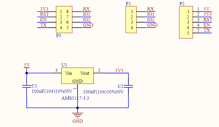
It perfectly matches the pins of the ESP8266 itself, and also adds a 5V pin to receive the voltage from the Arduino board. The integrated AMS1117 chip is used to drive the ESP8266 module after dropping the voltage to 3.3V.
The schematic diagram is as follows: