Note
Hello, welcome to the SunFounder Raspberry Pi & Arduino & ESP32 Enthusiasts Community on Facebook! Dive deeper into Raspberry Pi, Arduino, and ESP32 with fellow enthusiasts.
Why Join?
Expert Support: Solve post-sale issues and technical challenges with help from our community and team.
Learn & Share: Exchange tips and tutorials to enhance your skills.
Exclusive Previews: Get early access to new product announcements and sneak peeks.
Special Discounts: Enjoy exclusive discounts on our newest products.
Festive Promotions and Giveaways: Take part in giveaways and holiday promotions.
👉 Ready to explore and create with us? Click [here] and join today!
Bluetooth RGB Controller
This project uses an Android app to control the color of an RGB LED through Bluetooth technology using a smartphone.
This Android application will be constructed utilizing a complimentary web-based platform known as MIT App Inventor. The project presents an excellent opportunity to gain familiarity with the interfacing of an Arduino with a smartphone.
This project control an RGB LED connected to an Arduino Uno via a JDY-31 Bluetooth module. The Android application is used to send various color values to the Arduino Uno board via Bluetooth, based on user operations on the GUI. The program on Uno board receives RGB color values as characters from a serial port over Bluetooth and adjusts the LED’s color accordingly.
1. Build the Circuit

2. Create the Android App
The Android application will be developed using a free web application known as MIT App Inventor. MIT App Inventor serves as an excellent starting point for Android development, owing to its intuitive drag-and-drop features allowing for the creation of simplistic applications.
Now, let’s begin.
Go to Get Started with MIT App Inventor, and click “online tool” to login. You will require a Google account to register with MIT App Inventor.

After logging in, navigate to Projects -> Import project (.aia) from my computer. Subsequently, upload the
Control_RGB_LED.aiafile located in the pathultimate-sensor-kit\iot_project\bluetooth\04-Bluetooth_RGB_controller.You can also directly download here:
Control_RGB_LED.aia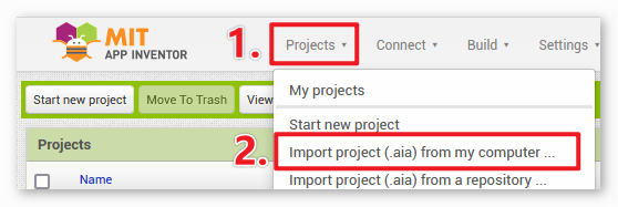
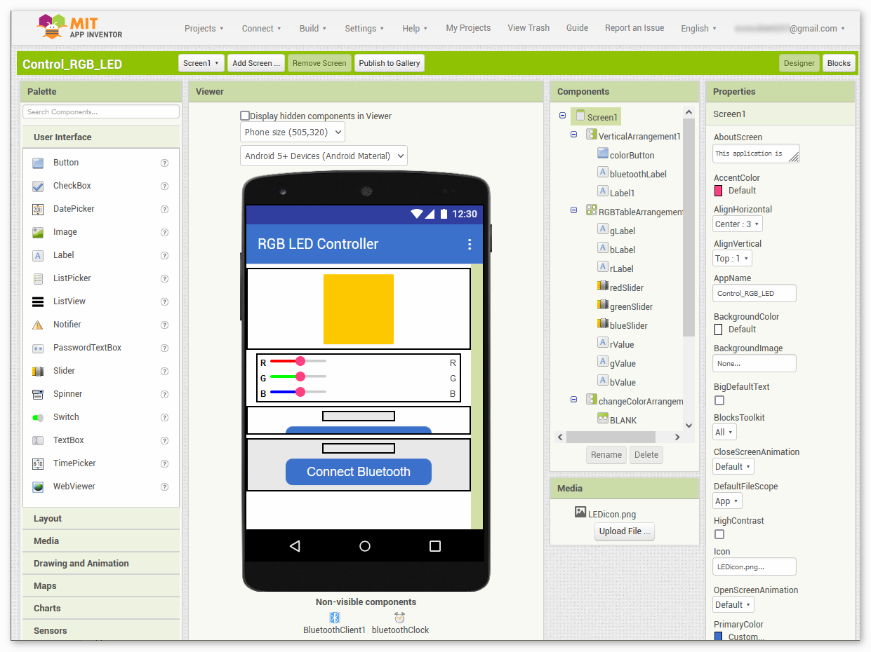
Upon uploading the
.aiafile, you will see the application on the MIT App Inventor software. This is a pre-configured template. You can modify this template after you have familiarized yourself with MIT App Inventor through the following steps.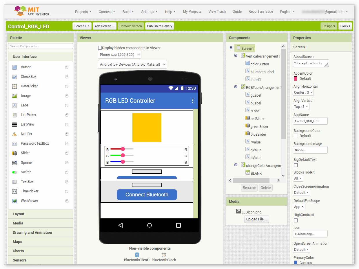
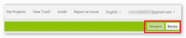
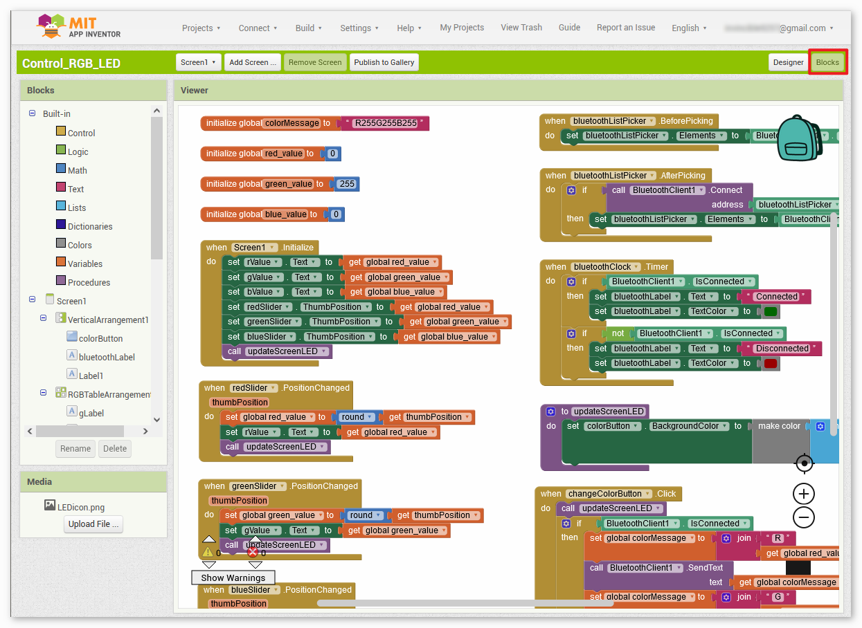
In MIT App Inventor, you have 2 primary sections: the Designer and the Blocks. You can switch between these two sections in the upper right corner of the page.
The Designer allows you to add buttons, text, screens, and modify the overall aesthetic of your application.
Next, there’s the Blocks section. This section lets you craft custom functionalities for your app, allowing you to program each component on the app’s GUI to achieve desired features.
To install the application on a smartphone, navigate to the Build tab.
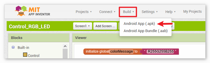
You can generate a
.apkfile. After selecting this option, a page will appear allowing you to choose between downloading a.apkfile or scanning a QR code for installation. Follow the installation guide to complete the application installation.You also download our pre-compiled APK here:
Control_RGB_LED.apkIf you wish to upload this app to Google Play or another app marketplace, you can generate a
.aabfile.
3. Upload the Code
Open the
04-Bluetooth_RGB_controller.inofile under the path ofultimate-sensor-kit\iot_project\bluetooth\04-Bluetooth_RGB_controller, or copy this code into Arduino IDE.After selecting the correct board and port, click the Upload button.
Open the Serial monitor(set baudrate to 9600) to view debug messages.
4. App and Bluetooth module Connection
Ensure that the application created earlier is installed on your smartphone.
Initially, turn on Bluetooth on your smartphone.
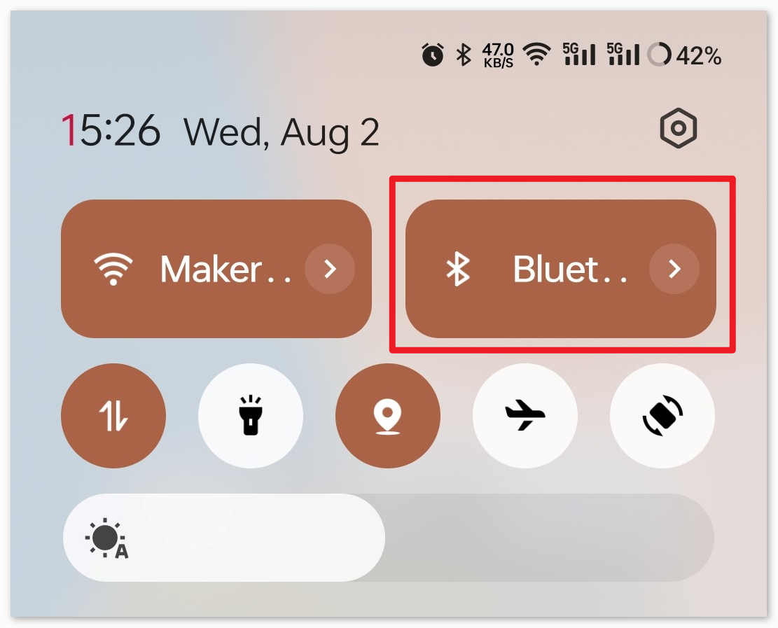
Navigate to the Bluetooth settings on your smartphone and look for names like JDY-31-SPP.

After clicking it, agree to the Pair request in the pop-up window. If prompted for a pairing code, please enter “1234”.

Now open the newly installed Control_RGB_LED APP.

In the APP, click on Connect Bluetooth to establish a connection between the APP and Bluetooth module.

This page displays a list of all paired Bluetooth devices. Choose the
xx.xx.xx.xx.xx.xx JDY-31-SPPoption from the list. The name of each device is listed next to its MAC address.
If you don’t see any devices on the page shown above, it could be because this app is not authorized to scan for nearby devices. In such a case, you will need to adjust the settings manually.
To access the APP Info page, long-press the app icon and select it. Alternatively, if you have another method to reach this page, use that instead.

Navigate to the Permissions page.

To enable the APP to scan for nearby devices, go to Nearby devices and select Always.

Now, restart the APP and repeat steps 5 and 6 to successfully connect to Bluetooth.
After successfully connecting, you will be redirected to the main page where it will show “connected”. From there, you can easily modify the RGB values and alter the color of the display by clicking on the Change Color button.

5. Code explanation
Setting up the Bluetooth module and initializing variables:
The code begins by including the
SoftwareSeriallibrary and initializing the necessary variables.#include <SoftwareSerial.h> SoftwareSerial bleSerial(3, 4); //Rx,Tx #define max_char 12 char message[max_char]; char r_char; byte currentIndex = 0; const int redPin = 9; const int greenPin = 10; const int bluePin = 11; int redValue = 0; int greenValue = 255; int blueValue = 0; String redTempValue; String greenTempValue; String blueTempValue; int flag = 0; char currentColor;
setup() function:
Here, the RGB LED pins are set as output pins, and the serial communication is initialized with a baud rate of 9600 for both the Arduino’s main serial and the Bluetooth module.
void setup() {
  pinMode(redPin, OUTPUT);
  pinMode(bluePin, OUTPUT);
  pinMode(greenPin, OUTPUT);
  Serial.begin(9600);
  bleSerial.begin(9600);
}
Reading and processing the data:
In the main loop, the code continuously checks for incoming data from the Bluetooth module. Upon receiving any data, it processes the characters to identify RGB values and sets the color of the RGB LED accordingly.
void loop() {
  while (bleSerial.available() > 0) {
    ... [data reading and processing]
  }

  if (flag == 0) {
    Serial.println(message);
    analogWrite(redPin, redTempValue.toInt());
    analogWrite(greenPin, greenTempValue.toInt());
    analogWrite(bluePin, blueTempValue.toInt());

    flag = 1;

    for (int i = 0; i < 12; i++) {
      message[i] = '\0';
    }
    currentIndex = 0;
  }
}