Note
Hello, welcome to the SunFounder Raspberry Pi & Arduino & ESP32 Enthusiasts Community on Facebook! Dive deeper into Raspberry Pi, Arduino, and ESP32 with fellow enthusiasts.
Why Join?
Expert Support: Solve post-sale issues and technical challenges with help from our community and team.
Learn & Share: Exchange tips and tutorials to enhance your skills.
Exclusive Previews: Get early access to new product announcements and sneak peeks.
Special Discounts: Enjoy exclusive discounts on our newest products.
Festive Promotions and Giveaways: Take part in giveaways and holiday promotions.
👉 Ready to explore and create with us? Click [here] and join today!
Bluetooth Traffic Light
This project is designed to control a traffic light (Red, Yellow, Green LEDs) using Bluetooth communication. The user can send a character (‘R’, ‘Y’, or ‘G’) from a Bluetooth device. When the Arduino receives one of these characters, it lights up the corresponding LED, while ensuring the other two LEDs are turned off.
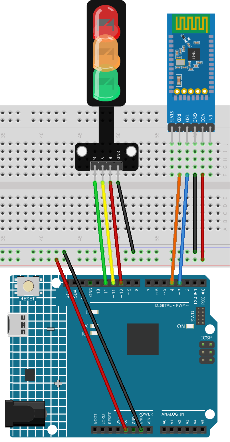
1. Build the Circuit
2. Upload the Code
Open the
02-Bluetooth_traffic_light.inofile under the path ofultimate-sensor-kit\iot_project\bluetooth\02-Bluetooth_traffic_light, or copy this code into Arduino IDE.After selecting the correct board and port, click the Upload button.
Open the Serial monitor(set baudrate to 9600) to view debug messages.
3. App and Bluetooth module Connection
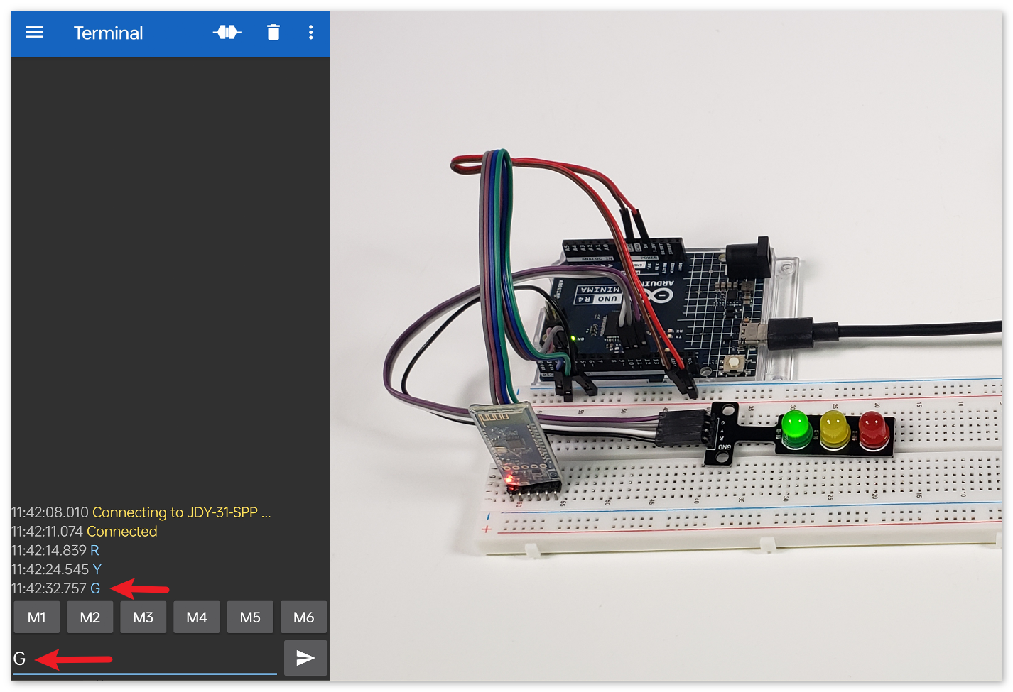
We can use an app called “Serial Bluetooth Terminal” to send messages from the Bluetooth module to Arduino.
Install Serial Bluetooth Terminal
Go to Google Play to download and install Serial Bluetooth Terminal .
Connect Bluetooth
Initially, turn on Bluetooth on your smartphone.
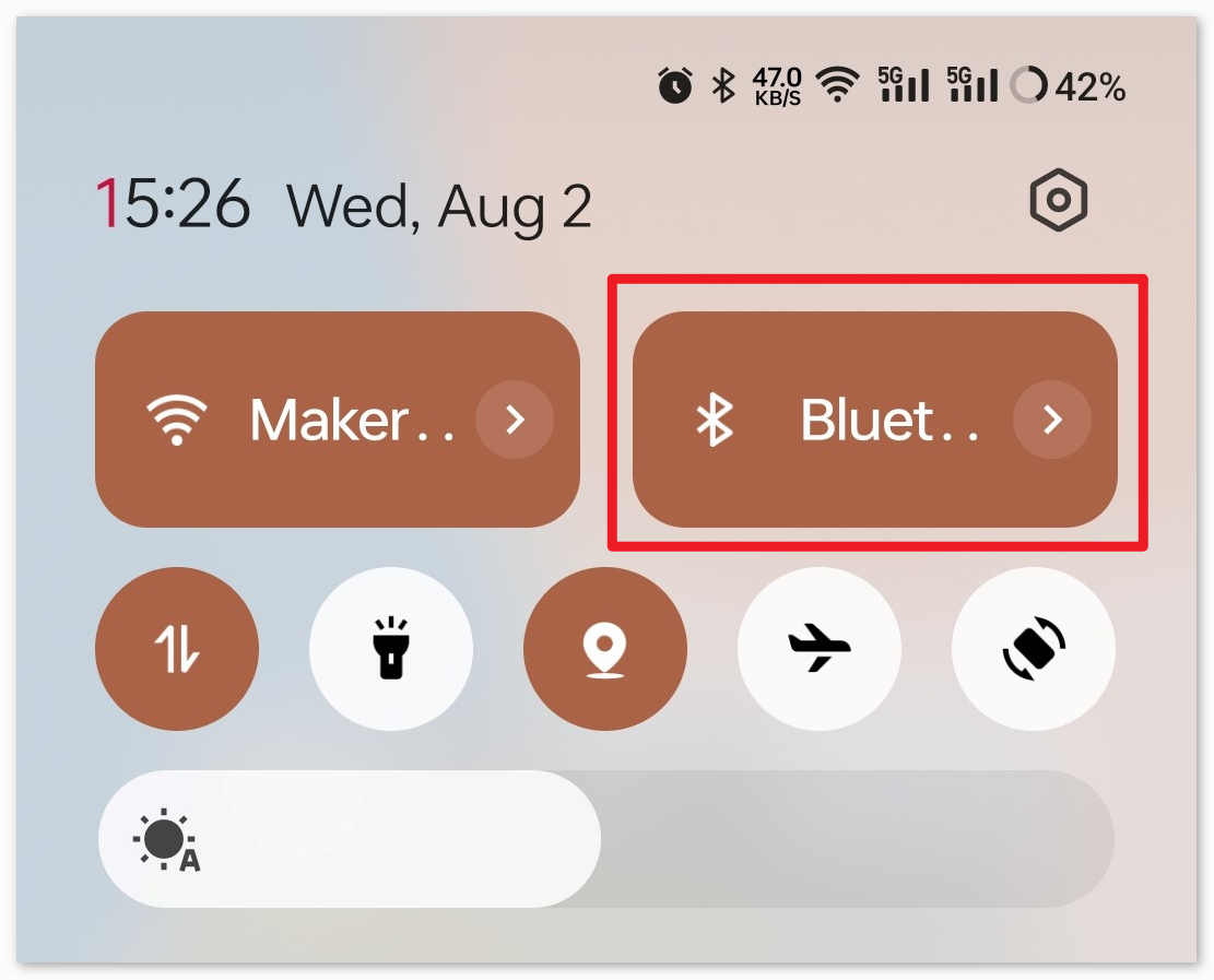
Navigate to the Bluetooth settings on your smartphone and look for names like JDY-31-SPP.

After clicking it, agree to the Pair request in the pop-up window. If prompted for a pairing code, please enter “1234”.

Communicate with Bluetooth module
Open the Serial Bluetooth Terminal. Connect to “JDY-31-SPP”.

Send command
Use the Serial Bluetooth Terminal app to send commands to Arduino via Bluetooth. Send R to turn on the red light, Y for yellow, and G for green.


4. Code explanation
Initialization and Bluetooth setup
// Set up Bluetooth module communication
#include <SoftwareSerial.h>
const int bluetoothTx = 3;
const int bluetoothRx = 4;
SoftwareSerial bleSerial(bluetoothTx, bluetoothRx);
We begin by including the SoftwareSerial library to help us with Bluetooth communication. The Bluetooth module’s TX and RX pins are then defined and associated with pins 3 and 4 on the Arduino. Finally, we initialize the
bleSerialobject for Bluetooth communication.LED Pin Definitions
// Pin numbers for each LED
const int rledPin = 10;  //red
const int yledPin = 11;  //yellow
const int gledPin = 12;  //green
Here, we’re defining which Arduino pins our LEDs are connected to. The red LED is on pin 10, yellow on 11, and green on 12.
setup() Function
void setup() {
   pinMode(rledPin, OUTPUT);
   pinMode(yledPin, OUTPUT);
   pinMode(gledPin, OUTPUT);

   Serial.begin(9600);
   bleSerial.begin(9600);
}
In the
setup()function, we set the LED pins asOUTPUT. We also start serial communication for both the Bluetooth module and the default serial (connected to the computer) at a baud rate of 9600.Main loop() for Bluetooth Communication
void loop() {
   while (bleSerial.available() > 0) {
      character = bleSerial.read();
      Serial.println(character);

      if (character == 'R') {
         toggleLights(rledPin);
      } else if (character == 'Y') {
         toggleLights(yledPin);
      } else if (character == 'G') {
         toggleLights(gledPin);
      }
   }
}
Inside our main
loop(), we continuously check if data is available from the Bluetooth module. If we receive data, we read the character and display it in the serial monitor. Depending on the character received (R, Y, or G), we toggle the respective LED using thetoggleLights()function.Toggle Lights Function
void toggleLights(int targetLight) {
   digitalWrite(rledPin, LOW);
   digitalWrite(yledPin, LOW);
   digitalWrite(gledPin, LOW);

   digitalWrite(targetLight, HIGH);
}
This function,
toggleLights(), turns off all the LEDs first. After ensuring they are all off, it turns on the specified target LED. This ensures that only one LED is on at a time.