Note
Hello, welcome to the SunFounder Raspberry Pi & Arduino & ESP32 Enthusiasts Community on Facebook! Dive deeper into Raspberry Pi, Arduino, and ESP32 with fellow enthusiasts.
Why Join?
Expert Support: Solve post-sale issues and technical challenges with help from our community and team.
Learn & Share: Exchange tips and tutorials to enhance your skills.
Exclusive Previews: Get early access to new product announcements and sneak peeks.
Special Discounts: Enjoy exclusive discounts on our newest products.
Festive Promotions and Giveaways: Take part in giveaways and holiday promotions.
👉 Ready to explore and create with us? Click [here] and join today!
L9110 Motor Driver Module
The L9110 motor driver module is adept at driving two motors in tandem. It houses a pair of independent L9110S driver chips, each channel boasting a steady current output of up to 800mA.
Spanning a voltage range from 2.5V to 12V, the module comfortably pairs with both 3.3V and 5V microcontrollers.
Serving as a streamlined solution, the L9110 motor driver module facilitates motor control across a spectrum of applications. Thanks to its dual-channel architecture, it enables the independent orchestration of two motors—ideal for projects where dual motor operations are paramount.
Given its potent continuous current output, this module confidently powers motors from the petite to the moderately sized, paving the way for diverse robotic, automation, and motor-centric endeavors. Its expansive voltage range further injects adaptability, aligning with varied power supply setups.
Designed with user-friendliness in mind, the module offers intuitive input and output terminals, simplifying connections to microcontrollers or akin control devices. Plus, it doesn’t skimp on safety—integrated overcurrent and overtemperature safeguards bolster the trustworthiness and security of motor operations.
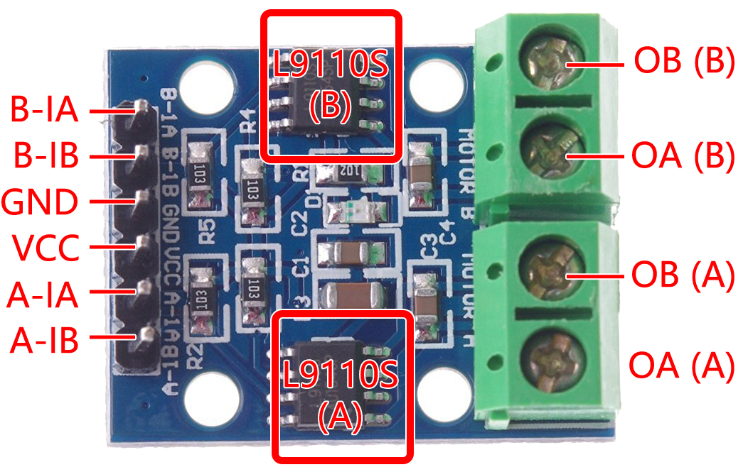
B-1A & B-1B(B-2A): Input pins for controlling the spinning direction of Motor B.
A-1A & A-1B: Input pins for controlling the spinning direction of Motor A.
0A & OB(A): Output pins of Motor A.
0A & OB(B): Output pins of Motor B.
VCC: Power input pin (2.5V-12V).
GND: Ground pin.
Features
On-board 2 L9110S motor control chip
Dual-channel motor control.
Independent motor spinning direction control.
High current output (800mA per channel).
Wide voltage range (2.5V-12V).
Compact design.
Convenient input and output terminals.
Built-in protective features.
Versatile applications.
PCB Size: 29.2mm x 23mm
Operating Temperature: -20°C ~ 80°C
Power-On LED indicator
Operating Principle
Here is the truth table of Motor B:
This truth table shows the different states of Motor B based on the values of input pins B-1A and B-1B(B-2A). It indicates the direction of rotation (clockwise or counterclockwise), braking, or stopping of Motor B.
B-1A |
B-1B(B-2A) |
The state of Motor B |
|---|---|---|
1 |
0 |
Rotate clockwise |
0 |
1 |
Rotate counterclockwise |
0 |
0 |
Brake |
1 |
1 |
Stop |
Here is the truth table of Motor A:
This truth table shows the different states of Motor A based on the values of input pins A-1A and A-1B. It indicates the direction of rotation (clockwise or counterclockwise), braking, or stopping of Motor A.
A-1A |
A-1B |
The state of Motor B |
|---|---|---|
1 |
0 |
Rotate clockwise |
0 |
1 |
Rotate counterclockwise |
0 |
0 |
Brake |
1 |
1 |
Stop |
1.3 Motor (Basic Project)
1. Move (Car Project)
3. Speed Up (Car Project)
8. IoT Car (IoT Project)