Note
Hello, welcome to the SunFounder Raspberry Pi & Arduino & ESP32 Enthusiasts Community on Facebook! Dive deeper into Raspberry Pi, Arduino, and ESP32 with fellow enthusiasts.
Why Join?
Expert Support: Solve post-sale issues and technical challenges with help from our community and team.
Learn & Share: Exchange tips and tutorials to enhance your skills.
Exclusive Previews: Get early access to new product announcements and sneak peeks.
Special Discounts: Enjoy exclusive discounts on our newest products.
Festive Promotions and Giveaways: Take part in giveaways and holiday promotions.
👉 Ready to explore and create with us? Click [here] and join today!
2.1.4 Potentiometer
Note
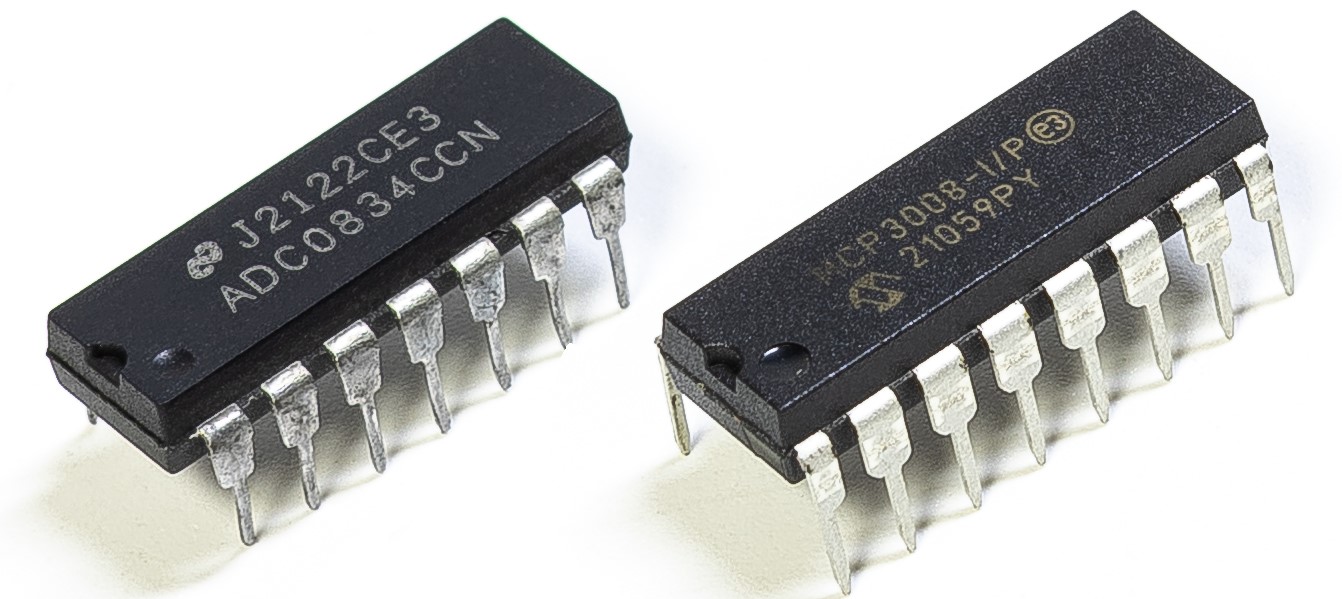
Depending on your kit version, please identify whether you have ADC0834 or MCP3008 and proceed with the matching section.
Introduction
The ADC function can be used to convert analog signals to digital signals, and in this experiment, ADC0834 is used to get the function involving ADC. Here, we implement this process by using potentiometer. Potentiometer changes the physical quantity – voltage, which is converted by the ADC function.
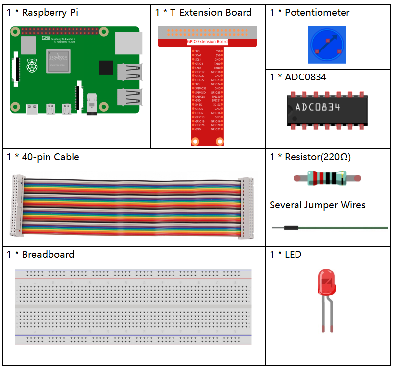
Required Components
In this project, we need the following components.
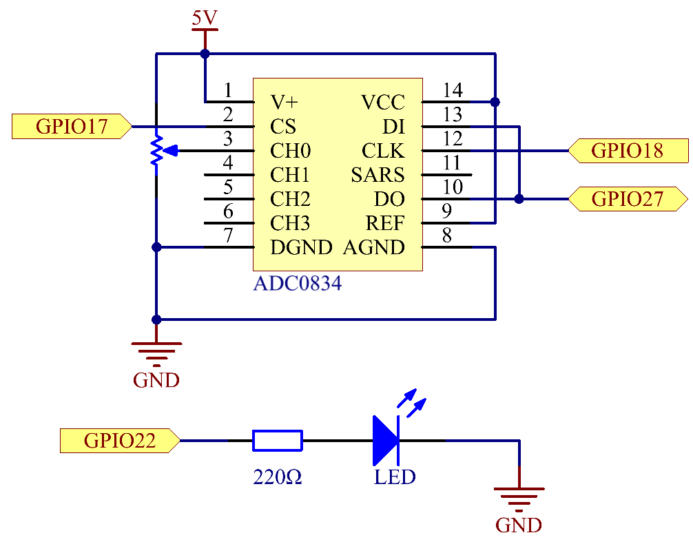
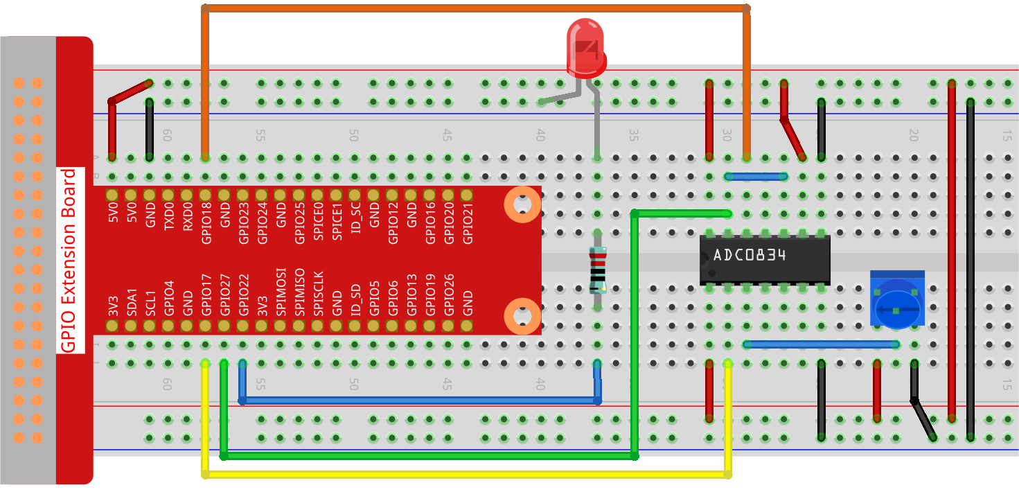
Schematic Diagram
Experimental Procedures
Step 1: Build the circuit.
Note
Please place the chip by referring to the corresponding position depicted in the picture. Note that the grooves on the chip should be on the left when it is placed.
Step 2: Open the code file
cd ~/davinci-kit-for-raspberry-pi/python-pi5
Step 3: Run.
sudo python3 2.1.4_Potentiometer.py
After the code runs, rotate the knob on the potentiometer, the intensity of LED will change accordingly.
Warning
If there is an error prompt RuntimeError: Cannot determine SOC peripheral base address, please refer to If gpiozero doesn’t work.
Code
Note
You can Modify/Reset/Copy/Run/Stop the code below. But before that, you need to go to source code path like davinci-kit-for-raspberry-pi/python-pi5. After modifying the code, you can run it directly to see the effect.
#!/usr/bin/env python3

from gpiozero import PWMLED
import ADC0834
import time

# Initialize a PWM LED on GPIO pin 22
led = PWMLED(22)

# Set up the ADC0834 module
ADC0834.setup()

def MAP(x, in_min, in_max, out_min, out_max):
    """
    Map a value from one range to another.
    :param x: The value to be mapped.
    :param in_min: The lower bound of the value's current range.
    :param in_max: The upper bound of the value's current range.
    :param out_min: The lower bound of the value's target range.
    :param out_max: The upper bound of the value's target range.
    :return: The mapped value.
    """
    return (x - in_min) * (out_max - out_min) / (in_max - in_min) + out_min

try:
    while True:
        # Get the current reading from the ADC0834 module
        res = ADC0834.getResult()
        print('res = %d' % res)

        # Map the ADC value to a range suitable for setting LED brightness
        R_val = MAP(res, 0, 255, 0, 100)

        # Set the LED brightness
        led.value = float(R_val / 100)

        # Wait for 0.2 seconds before reading again
        time.sleep(0.2)

# Graceful exit when 'Ctrl+C' is pressed
except KeyboardInterrupt:
    led.value = 0  # Turn off the LED
Code Explanation
gpiozerofor PWM LED control,ADC0834for analog-to-digital conversion, andtimefor implementing delays.#!/usr/bin/env python3 from gpiozero import PWMLED import ADC0834 import time
Initialize a PWMLED object connected to GPIO pin 22 and set up the ADC0834 converter.
# Initialize a PWM LED on GPIO pin 22
led = PWMLED(22)

# Set up the ADC0834 module
ADC0834.setup()
Define a function named
MAPto convert one range of values to another, useful for mapping ADC values to appropriate LED brightness levels.def MAP(x, in_min, in_max, out_min, out_max): return (x - in_min) * (out_max - out_min) / (in_max - in_min) + out_min
Continuously read the ADC value in a loop, mapping the ADC reading (0-255) to a brightness level (0-100) for the LED. Adjust the LED’s brightness based on this mapped value. Implement a delay of 0.2 seconds for better readability and stability.
try:
    while True:
        # Get the current reading from the ADC0834 module
        res = ADC0834.getResult()
        print('res = %d' % res)

        # Map the ADC value to a range suitable for setting LED brightness
        R_val = MAP(res, 0, 255, 0, 100)

        # Set the LED brightness
        led.value = float(R_val / 100)

        # Wait for 0.2 seconds before reading again
        time.sleep(0.2)

# Graceful exit when 'Ctrl+C' is pressed
except KeyboardInterrupt:
    led.value = 0  # Turn off the LED