Note
Hello, welcome to the SunFounder Raspberry Pi & Arduino & ESP32 Enthusiasts Community on Facebook! Dive deeper into Raspberry Pi, Arduino, and ESP32 with fellow enthusiasts.
Why Join?
Expert Support: Solve post-sale issues and technical challenges with help from our community and team.
Learn & Share: Exchange tips and tutorials to enhance your skills.
Exclusive Previews: Get early access to new product announcements and sneak peeks.
Special Discounts: Enjoy exclusive discounts on our newest products.
Festive Promotions and Giveaways: Take part in giveaways and holiday promotions.
👉 Ready to explore and create with us? Click [here] and join today!
1.1.4 7-segment Display
Introduction
Let’s try to drive a 7-segment display to show a figure from 0 to 9 and A to F.
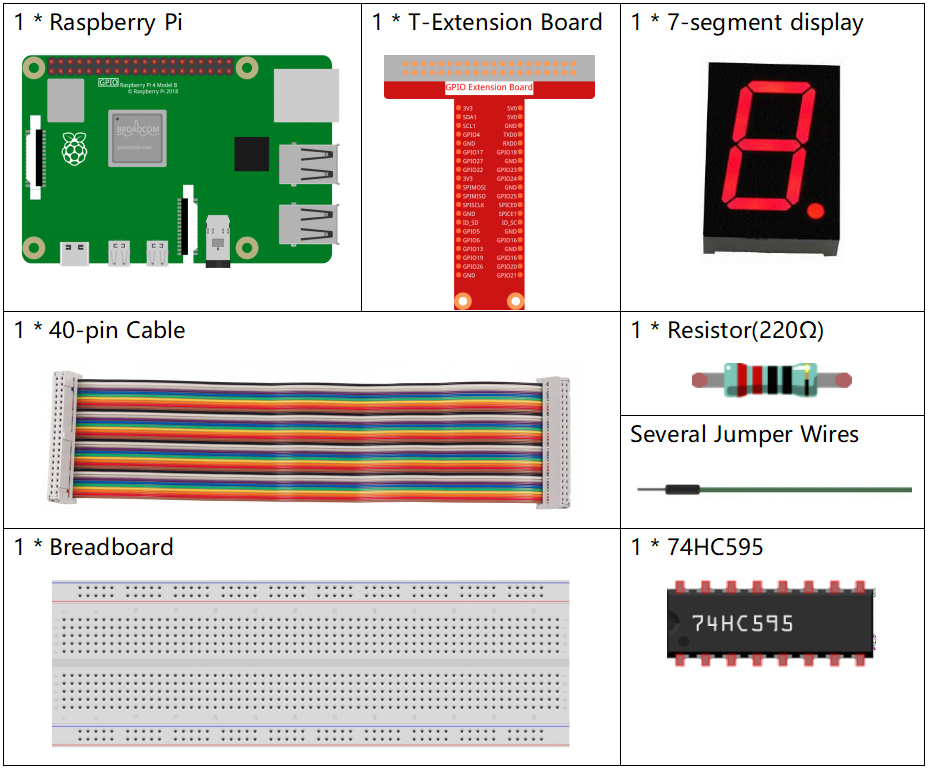
Required Components
In this project, we need the following components.
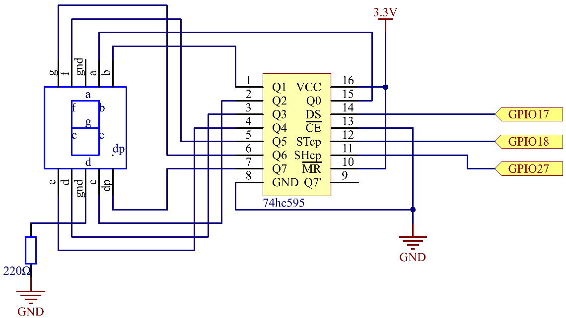
Schematic Diagram
Connect pin ST_CP of 74HC595 to Raspberry Pi GPIO18, SH_CP to GPIO27, DS to GPIO17, parallel output ports to 8 segments of the LED segment display.
Input data in DS pin to shift register when SH_CP (the clock input of the shift register) is at the rising edge, and to the memory register when ST_CP (the clock input of the memory) is at the rising edge.
Then you can control the states of SH_CP and ST_CP via the Raspberry Pi GPIOs to transform serial data input into parallel data output so as to save Raspberry Pi GPIOs and drive the display.
T-Board Name |
physical |
BCM |
GPIO17 |
Pin 11 |
17 |
GPIO18 |
Pin 12 |
18 |
GPIO27 |
Pin 13 |
27 |
Experimental Procedures
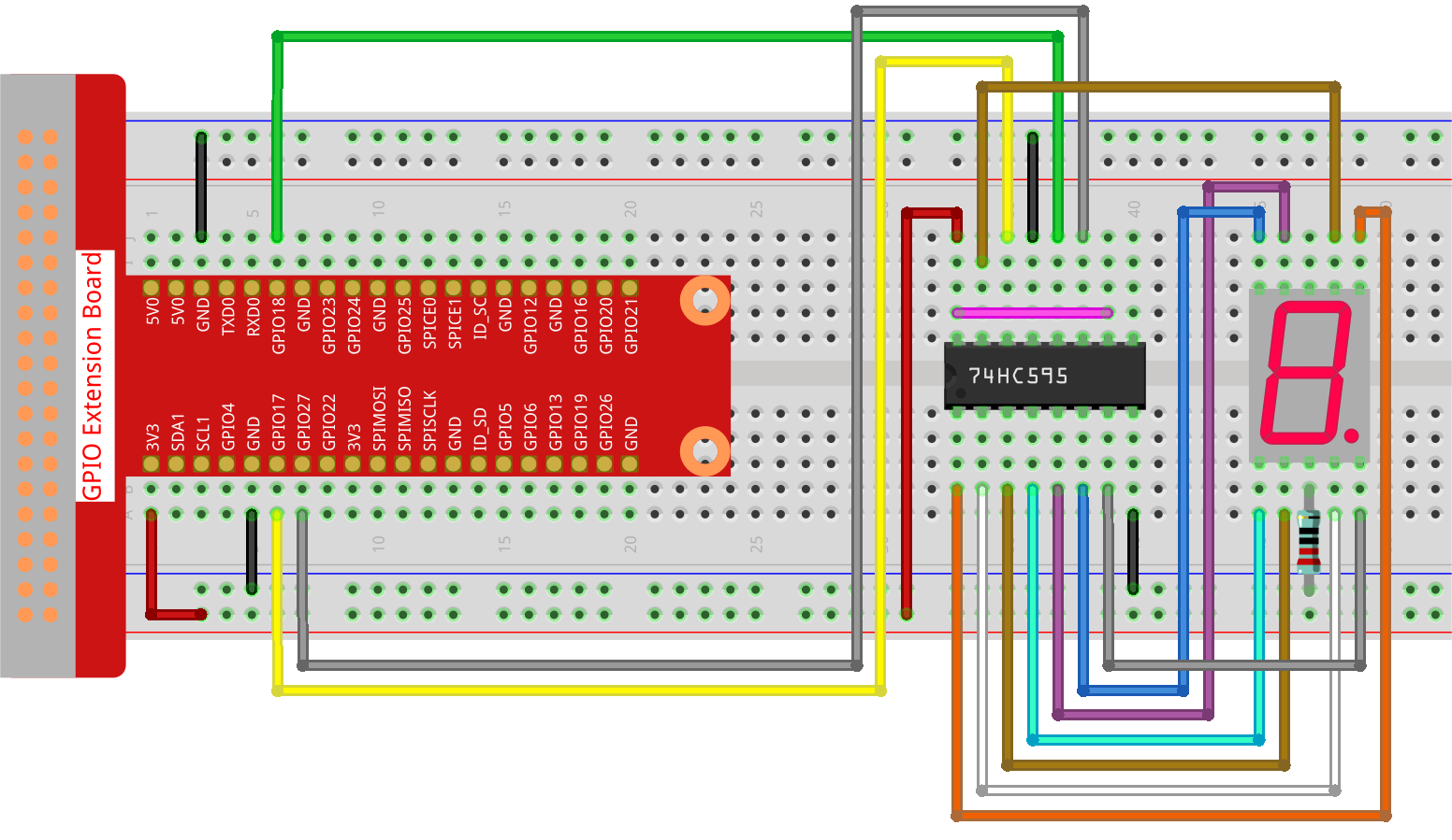
Step 1: Build the circuit.
Step 2: Get into the folder of the code.
cd ~/davinci-kit-for-raspberry-pi/python-pi5
Step 3: Run.
sudo python3 1.1.4_7-Segment.py
After the code runs, you’ll see the 7-segment display display 0-9, A-F.
Warning
If there is an error prompt RuntimeError: Cannot determine SOC peripheral base address, please refer to If gpiozero doesn’t work.
Code
Note
You can Modify/Reset/Copy/Run/Stop the code below. But before that, you need to go to source code path like davinci-kit-for-raspberry-pi/python-pi5. After modifying the code, you can run it directly to see the effect. After confirming that there are no problems, you can use the Copy button to copy the modified code, then open the source code in Terminal via nano cammand and paste it.
#!/usr/bin/env python3
from gpiozero import OutputDevice
from time import sleep

# GPIO pins connected to 74HC595 shift register
SDI = OutputDevice(17)   # Serial Data Input
RCLK = OutputDevice(18)  # Memory Clock Input (Register Clock)
SRCLK = OutputDevice(27) # Shift Register Clock

# Hexadecimal digit codes for a common cathode 7-segment display
segCode = [
    0x3f, 0x06, 0x5b, 0x4f, 0x66, 0x6d, 0x7d,
    0x07, 0x7f, 0x6f, 0x77, 0x7c, 0x39, 0x5e, 0x79, 0x71
]

def hc595_shift(data):
    # Shift 8 bits of data into the 74HC595
    for bit in range(8):
        # Set SDI high or low based on data bit
        SDI.value = 0x80 & (data << bit)
        # Trigger shift register clock
        SRCLK.on()
        sleep(0.001)
        SRCLK.off()
    # Latch data to output by triggering memory clock
    RCLK.on()
    sleep(0.001)
    RCLK.off()

def display_all_on():
    # Function to turn all segments on (for common cathode 7-segment display)
    all_on_code = 0x3f
    hc595_shift(all_on_code)
    print("Displaying all segments on")

try:
    while True:
        # Display each hexadecimal digit on 7-segment display
        for code in segCode:
            hc595_shift(code)  # Shift the code into 74HC595
            # Print the displayed segment code
            print(f"Displaying segCode[{segCode.index(code)}]: 0x{code:02X}")
            sleep(0.5)  # Pause between displaying each digit

except KeyboardInterrupt:
    # Gracefully handle script interruption (e.g., Ctrl+C)
    pass
Code Explanation
This snippet imports the necessary classes for the project.
OutputDevicefromgpiozerois used to control hardware components connected to GPIO pins, andsleepfromtimeis for adding delays.#!/usr/bin/env python3 from gpiozero import OutputDevice from time import sleep
SDI, RCLK, and SRCLK correspond to the Serial Data Input, Memory Clock Input (Register Clock), and Shift Register Clock pins of the 74HC595.
# GPIO pins connected to 74HC595 shift register
SDI = OutputDevice(17)   # Serial Data Input
RCLK = OutputDevice(18)  # Memory Clock Input (Register Clock)
SRCLK = OutputDevice(27) # Shift Register Clock
segCodeis an array containing hexadecimal codes for each digit to be displayed on the 7-segment display.# Hexadecimal digit codes for a common cathode 7-segment display segCode = [ 0x3f, 0x06, 0x5b, 0x4f, 0x66, 0x6d, 0x7d, 0x07, 0x7f, 0x6f, 0x77, 0x7c, 0x39, 0x5e, 0x79, 0x71 ]
This function shifts 8 bits of data into the 74HC595. It serially inputs each bit into
SDI, togglesSRCLKto shift the bit, and usesRCLKto latch the data to the output.def hc595_shift(data): # Shift 8 bits of data into the 74HC595 for bit in range(8): # Set SDI high or low based on data bit SDI.value = 0x80 & (data << bit) # Trigger shift register clock SRCLK.on() sleep(0.001) SRCLK.off() # Latch data to output by triggering memory clock RCLK.on() sleep(0.001) RCLK.off()
This function turns all segments of the display on by sending a specific code to
hc595_shift.def display_all_on(): # Function to turn all segments on (for common cathode 7-segment display) all_on_code = 0x3f hc595_shift(all_on_code) print("Displaying all segments on")
In the main loop, each code in
segCodeis sent to the display in sequence, with a delay between each.try: while True: # Display each hexadecimal digit on 7-segment display for code in segCode: hc595_shift(code) # Shift the code into 74HC595 # Print the displayed segment code print(f"Displaying segCode[{segCode.index(code)}]: 0x{code:02X}") sleep(0.5) # Pause between displaying each digit
This part of the code gracefully handles script interruption (like Ctrl+C).
except KeyboardInterrupt:
    # Gracefully handle script interruption (e.g., Ctrl+C)
    pass