Note
Hello, welcome to the SunFounder Raspberry Pi & Arduino & ESP32 Enthusiasts Community on Facebook! Dive deeper into Raspberry Pi, Arduino, and ESP32 with fellow enthusiasts.
Why Join?
Expert Support: Solve post-sale issues and technical challenges with help from our community and team.
Learn & Share: Exchange tips and tutorials to enhance your skills.
Exclusive Previews: Get early access to new product announcements and sneak peeks.
Special Discounts: Enjoy exclusive discounts on our newest products.
Festive Promotions and Giveaways: Take part in giveaways and holiday promotions.
👉 Ready to explore and create with us? Click [here] and join today!
1.1.2 RGB LED
Introduction
In this project, we will control an RGB LED to flash various colors.
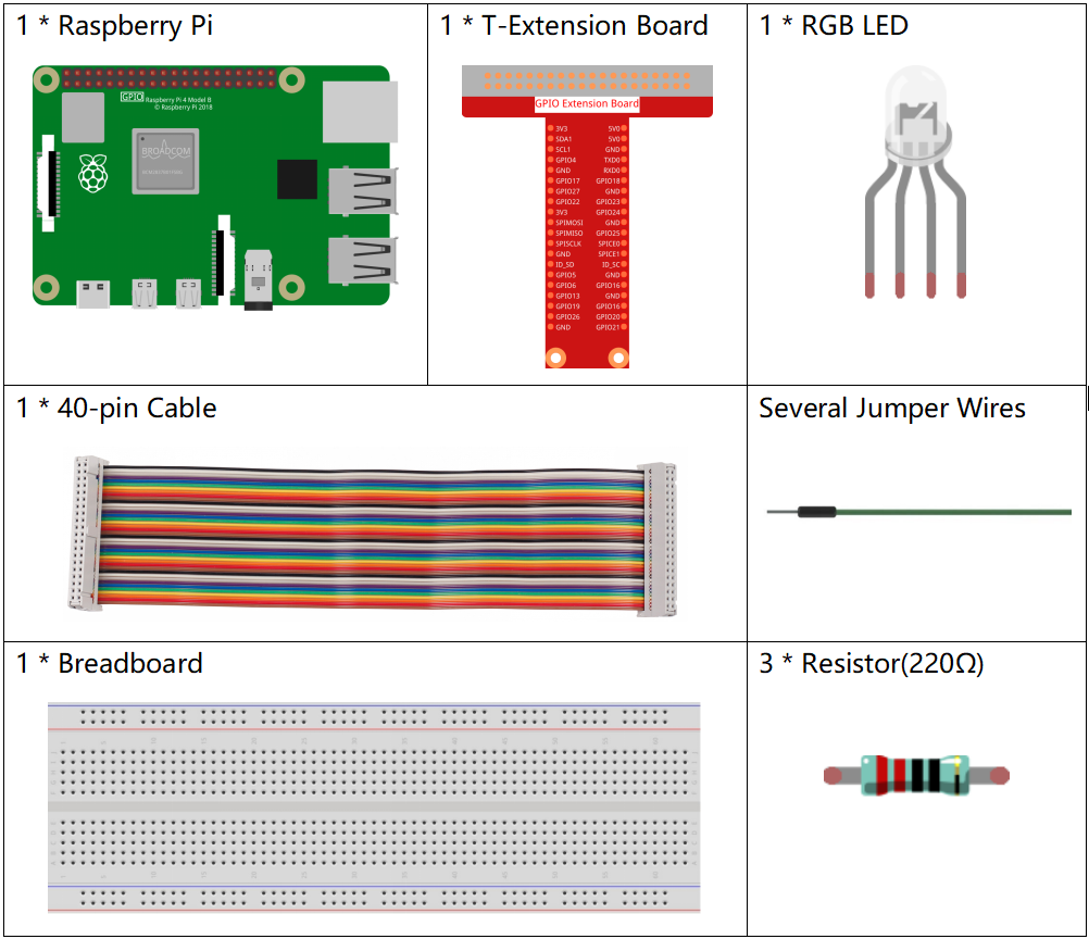
Required Components
In this project, we need the following components.
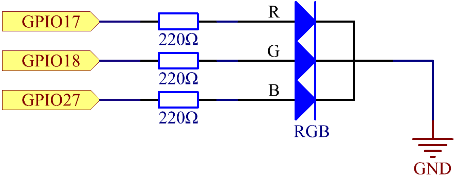
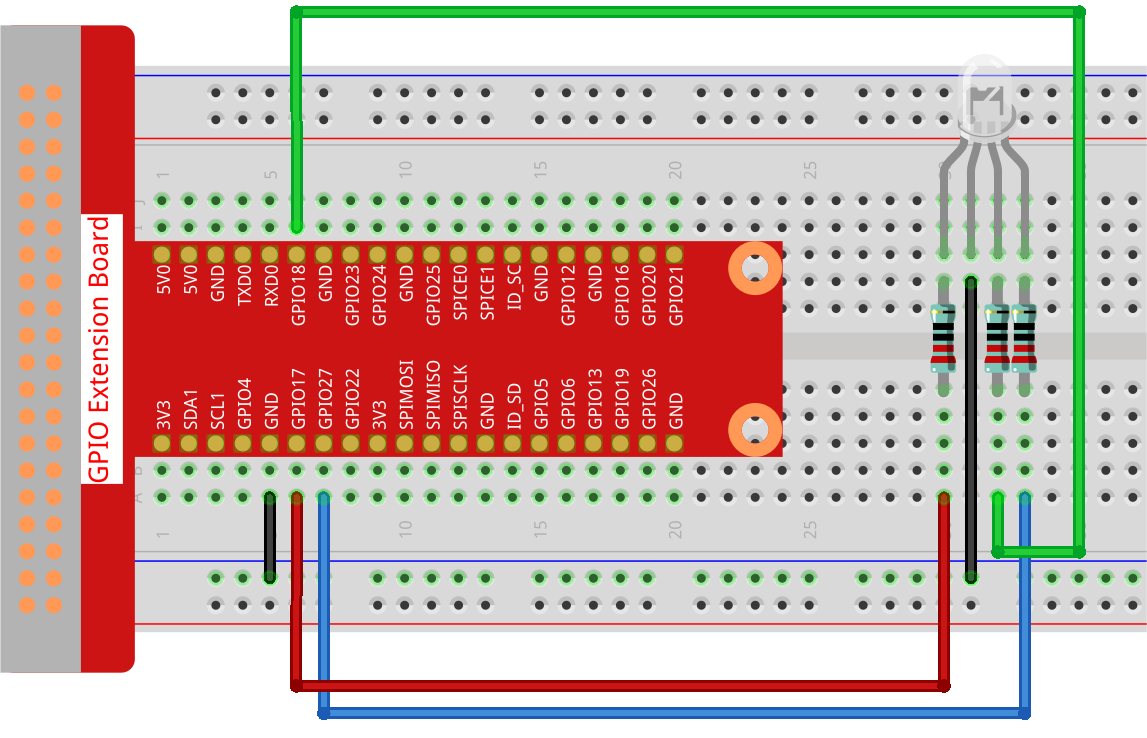
Schematic Diagram
After connecting the pins of R, G, and B to a current limiting resistor, connect them to the GPIO17, GPIO18, and GPIO27 respectively. The longest pin (GND) of the LED connects to the GND of the Raspberry Pi. When the three pins are given different PWM values, the RGB LED will display different colors.
T-Board Name |
physical |
BCM |
GPIO17 |
Pin 11 |
17 |
GPIO18 |
Pin 12 |
18 |
GPIO27 |
Pin 13 |
27 |
Experimental Procedures
Step 1: Build the circuit.
Step 2: Open the code file.
cd ~/davinci-kit-for-raspberry-pi/python-pi5
Step 3: Run.
sudo python3 1.1.2_rgbLed.py
After the code runs, you will see that RGB displays red, green, blue, yellow, pink, and cyan.
Warning
If there is an error prompt RuntimeError: Cannot determine SOC peripheral base address, please refer to If gpiozero doesn’t work.
Code
Note
You can Modify/Reset/Copy/Run/Stop the code below. But before that, you need to go to source code path like davinci-kit-for-raspberry-pi/python-pi5. After modifying the code, you can run it directly to see the effect.
#!/usr/bin/env python3
from gpiozero import RGBLED
from time import sleep

# Define a list of colors for the RGB LED in RGB format (Red, Green, Blue).
# Each color component ranges from 0 (off) to 1 (full intensity).
COLORS = [(1, 0, 0), (0, 1, 0), (0.2, 0.1, 1), (1, 1, 0), (1, 0, 1), (0, 1, 1)]

# Initialize an RGB LED. Connect the red component to GPIO 17, green to GPIO 18, and blue to GPIO 27.
rgb_led = RGBLED(red=17, green=18, blue=27)

try:
    # Continuously cycle through the defined colors.
    while True:
        for color in COLORS:
            # Set the RGB LED to the current color.
            rgb_led.color = color
            # Output the current color to the console.
            print(f"Color set to: {color}")
            # Wait for 1 second before switching to the next color.
            sleep(1)

except KeyboardInterrupt:
    # Handle a KeyboardInterrupt (Ctrl+C) to exit the loop gracefully.
    # GPIO cleanup will be managed automatically by GPIO Zero on script termination.
    pass
Code Explanation
This imports the
RGBLEDclass from thegpiozerolibrary for controlling an RGB LED, and thetimelibrary for implementing delays in the code.#!/usr/bin/env python3 from gpiozero import RGBLED from time import sleep # Define a list of colors for the RGB LED in RGB format (Red, Green, Blue). # Each color component ranges from 0 (off) to 1 (full intensity).
The
COLORSlist contains tuples representing different colors in RGB format. By assigning different Pulse Width Modulation (PWM) values to each of the R, G, and B pins through thergb_led.colorattribute, the LED can produce a variety of colors. The PWM values range from 0 to 1, where 0 represents no intensity (off) and 1 represents full intensity for each color component.For instance, setting
rgb_led.color = (1, 0, 0)turns the LED red, as it sets full intensity for the red component while keeping green and blue off. Similarly, varying combinations of these values result in different colors. This technique of color mixing through PWM allows for the creation of a wide range of colors on the RGB LED.COLORS = [(1, 0, 0), (0, 1, 0), (0.2, 0.1, 1), (1, 1, 0), (1, 0, 1), (0, 1, 1)]
An RGB LED is initialized with its red, green, and blue components connected to GPIO pins 17, 18, and 27, respectively.
# Initialize an RGB LED. Connect the red component to GPIO 17, green to GPIO 18, and blue to GPIO 27.
rgb_led = RGBLED(red=17, green=18, blue=27)
The
while True:loop continuously cycles through the colors defined inCOLORS. For each color,rgb_led.color = colorsets the LED to that color, andsleep(1)pauses for 1 second.try: # Continuously cycle through the defined colors. while True: for color in COLORS: # Set the RGB LED to the current color. rgb_led.color = color # Output the current color to the console. print(f"Color set to: {color}") # Wait for 1 second before switching to the next color. sleep(1)
This section gracefully handles a
KeyboardInterrupt(such as pressing Ctrl+C). Thepassstatement is used as a placeholder to indicate no specific action on interruption, as GPIO Zero handles GPIO cleanup automatically.except KeyboardInterrupt: # Handle a KeyboardInterrupt (Ctrl+C) to exit the loop gracefully. # GPIO cleanup will be managed automatically by GPIO Zero on script termination. pass