Note
Hello, welcome to the SunFounder Raspberry Pi & Arduino & ESP32 Enthusiasts Community on Facebook! Dive deeper into Raspberry Pi, Arduino, and ESP32 with fellow enthusiasts.
Why Join?
Expert Support: Solve post-sale issues and technical challenges with help from our community and team.
Learn & Share: Exchange tips and tutorials to enhance your skills.
Exclusive Previews: Get early access to new product announcements and sneak peeks.
Special Discounts: Enjoy exclusive discounts on our newest products.
Festive Promotions and Giveaways: Take part in giveaways and holiday promotions.
👉 Ready to explore and create with us? Click [here] and join today!
Show Number
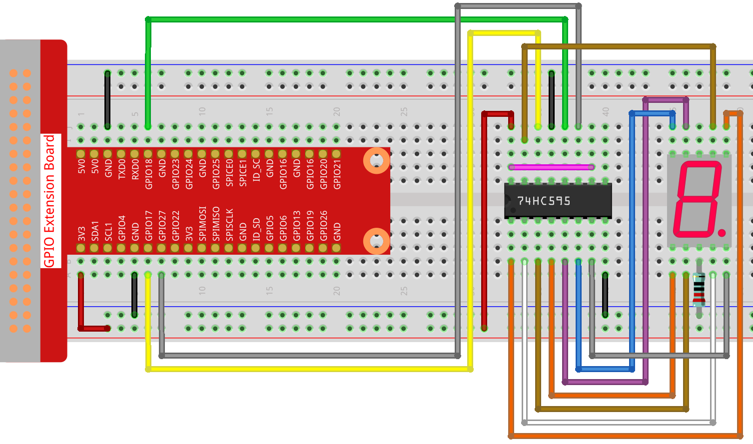
In this lesson, we use processing to drive a 7-segment display to show a figure from 0 to 9 and A to F.
Wiring
Sketch
import processing.io.*;

int SDI=17;   //serial data input
int RCLK=18;  //memory clock input(STCP)
int SRCLK =27;   //shift register clock input(SHCP)


int[] SegCode= {0x3f,0x06,0x5b,0x4f,0x66,0x6d,0x7d,0x07,0x7f,0x6f,0x77,0x7c,0x39,0x5e,0x79,0x71};

void hc595_shift(int dat){
  int i;

  for(i=0;i<8;i++){
        int n=(0x80 & (dat << i));
        if ( n==0){
          GPIO.digitalWrite(SDI, 0);
        } else {
          GPIO.digitalWrite(SDI, 1);
        }
        GPIO.digitalWrite(SRCLK, 1);
        delay(1);
        GPIO.digitalWrite(SRCLK, 0);
  }

        GPIO.digitalWrite(RCLK, 1);
        delay(1);
        GPIO.digitalWrite(RCLK, 0);
}

void setup() {
        size(400, 200);
        frameRate(10);

        GPIO.pinMode(SDI, GPIO.OUTPUT);
        GPIO.pinMode(RCLK, GPIO.OUTPUT);
        GPIO.pinMode(SRCLK, GPIO.OUTPUT);

        GPIO.digitalWrite(SDI, 0);
        GPIO.digitalWrite(RCLK, 0);
        GPIO.digitalWrite(SRCLK, 0);

        fill(0,25,88);
        textAlign(CENTER,CENTER);
        textSize(height*0.8);
}

void draw() {

        background(255);
        int number = (frameCount%100)/10;
        text(number, width/2, height/2);
        hc595_shift(SegCode[number]);
}
How it works?
Import processing.io.* and use the GPIO function library to control the digital tube pins.
Define array SegCode = {0x3f,0x06,0x5b,0x4f,0x66,0x6d,0x7d,0x07,0x7f,0x6f,0x77,0x7c,0x39,0x5e,0x79,0x71}
which represents a segment code array from 0 to F in Hexadecimal (Common cathode).
setup() function sets the three pins SDI,RCLK and SRCLK as output, and the initial data as 0.
hc595_shift(int dat) function is used to shift the SegCode to 74HC595.
void hc595_shift(int dat){
  int i;

  for(i=0;i<8;i++){
        int n=(0x80 & (dat << i));
        if ( n==0){
          GPIO.digitalWrite(SDI, 0);
        } else {
          GPIO.digitalWrite(SDI, 1);
        }
        GPIO.digitalWrite(SRCLK, 1);
        delay(1);
        GPIO.digitalWrite(SRCLK, 0);
  }

        GPIO.digitalWrite(RCLK, 1);
        delay(1);
        GPIO.digitalWrite(RCLK, 0);
}
n=(0x80 & (dat << i)) means to shift dat to the left by i bits and then do the & operation with 0x80.
The rule of & operation is that when both sides of & are 1, the result is 1, otherwise the result is 0.
For example, we assume dat=0x3f,i=2(0011 1111 << 2 shift to 1111 1100), then 1111 1100 & 1000 0000 (0x80)) = 1000 0000.
At last assign the dat data to SDI(DS) by bits.
digitalWrite(SRCLK, 1) when SRCLK generates a rising edge pulse from 0 to 1, the data will be transferred from the DS register to the shift register;
digitalWrite(RCLK, 1) when RCLK generates a rising edge pulse from 0 to 1, the data will be transferred from the shift register to the storage register.
fill(0,25,88);
textAlign(CENTER,CENTER);
textSize(height*0.8);
fill(): Sets the color used to fill shapes.textAlign(CENTER,CENTER): Sets the current alignment for drawing text. The parametersLEFT,CENTER, andRIGHTset the display characteristics of the letters in relation to the values for the x and y parameters of thetext()function.textSize(): Sets the current font size. This size will be used in all subsequent calls to thetext()function. Font size is measured in units of pixels.
These functions can customize the text style displayed on the processing.
void draw() {

        background(255);
        int number = (frameCount%100)/10;
        text(number, width/2, height/2);
        hc595_shift(SegCode[number]);
}
The frameCount is a seed, which is related to frameRate.
By default frameRate is 60, which means that frameCount will accumulate 60 times per second.
Then we can let processing and 7-segment display to show the figure from 0 to 9 and A to F simultaneously.
For more please refer to Processing Reference.