2. Move by Code
In the previous project, we have tried to control the operation of the motor by using different level signals for the input of the L298N.
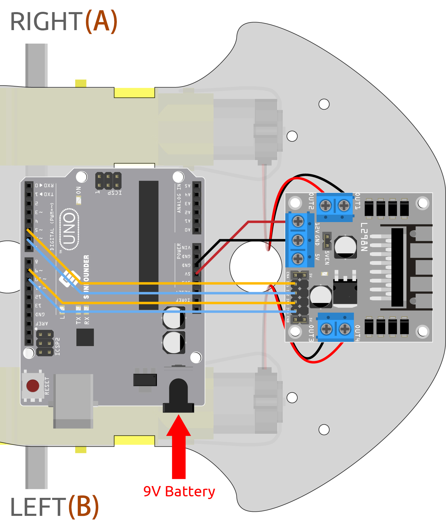
If we modify the level signals through the program, then we can control the movement of the car in a flexible way. Here we connect the pins IN1~IN4 of L298N to pins 5, 6, 9 and 10 on the R3 board in turn.
Required Components
In this project, we need the following components.
It’s definitely convenient to buy a whole kit, here’s the link:
Name |
ITEMS IN THIS KIT |
LINK |
|---|---|---|
3 in 1 Starter Kit |
380+ |
You can also buy them separately from the links below.
COMPONENT INTRODUCTION |
PURCHASE LINK |
|---|---|
- |
Wiring
The L298N motor driver module is a high power motor driver module for driving DC and stepper motors. The L298N module can control up to 4 DC motors, or 2 DC motors with direction and speed control.
Connect the wires between the L298N module and the R3 board according to the diagram below.
L298N |
R3 Board |
Motor |
|---|---|---|
IN1 |
5 |
|
IN2 |
6 |
|
IN3 |
9 |
|
IN4 |
10 |
|
OUT1 |
Black wire of right motor |
|
OUT2 |
Red wire of right motor |
|
OUT3 |
Black wire of left motor |
|
OUT4 |
Red wire of left motor |
Code
Note
Open the
2.move.inofile under the path of3in1-kit\car_project\2.move.Or copy this code into Arduino IDE.
Or upload the code through the Arduino Web Editor.
After the code is uploaded, the car will move forward, backward, left and right for two seconds respectively.
How it works?
This project is basically the same as the previous one, which is to make the car move forward, backward, left and right and stop by giving different levels from IN1 to IN4.
Initialize the pin wiring of IN1~IN4.
const int in1 = 5;
const int in2 = 6;
const int in3 = 9;
const int in4 = 10;

void setup() {
    pinMode(in1, OUTPUT);
    pinMode(in2, OUTPUT);
    pinMode(in3, OUTPUT);
    pinMode(in4, OUTPUT);
}
Set IN1~IN4 to different high or low levels to control the rotation of the left and right motors, and then encapsulate them in individual functions.
void moveForward() {
    digitalWrite(in1, LOW);
    digitalWrite(in2, HIGH);
    digitalWrite(in3, HIGH);
    digitalWrite(in4, LOW);
}

void moveBackward() {
    digitalWrite(in1, HIGH);
    digitalWrite(in2, LOW);
    digitalWrite(in3, LOW);
    digitalWrite(in4, HIGH);
}
...
Call these functions in
loop().void loop() { moveForward(); delay(2000); stopMove(); delay(500); moveBackward(); delay(2000); stopMove(); delay(500); ...
-
pin: the Arduino pin number.value: HIGH or LOW.
Write a HIGH or a LOW value to a digital pin. If the pin has been configured as an
OUTPUTwithpinMode(), its voltage will be set to the corresponding value: 5V (or 3.3V on 3.3V boards) for HIGH, 0V (ground) for LOW. -
pin: the Arduino pin number to set the mode of.mode: INPUT, OUTPUT, or INPUT_PULLUP.
Configures the specified pin to behave either as an input or an output.
-
ms: the number of milliseconds to pause. Allowed data types: unsigned long.
Pauses the program for the amount of time (in milliseconds) specified as parameter. (There are 1000 milliseconds in a second.)