1. Move
Before we start programming, let’s review the working principle of L298N.
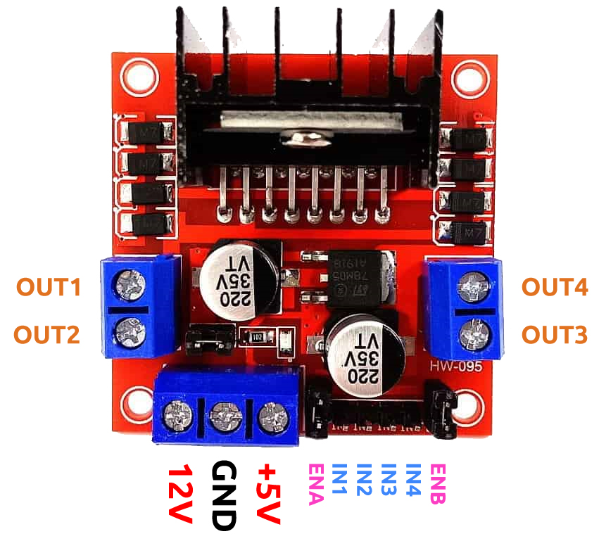
IN1~IN4 are the inputs of the L298N module, and OUT1~OUT4 are the outputs.
A simple way to use them is: input high level for IN1, OUT1 will output high level; input low level for IN1, OUT1 will output low level. Connecting the two ends of the motor to OUT1 and OUT2, inputting opposite level signals for IN1 and IN2 will make the motor rotate.OUT3 and OUT4 can be used in the same way.
The working relationship between ENA and IN1,IN2 is as follows.
ENA |
IN1 |
IN2 |
The state of right motor(A) |
|---|---|---|---|
0 |
X |
X |
Stop |
1 |
0 |
0 |
Brake |
1 |
0 |
1 |
Rotate clockwise |
1 |
1 |
0 |
Rotate counterclockwise |
1 |
1 |
1 |
Brake |
The working relationship between ENB and IN3,IN4 is as follows.
ENB |
IN3 |
IN4 |
The state of left motor(B) |
|---|---|---|---|
0 |
X |
X |
Stop |
1 |
0 |
0 |
Brake |
1 |
0 |
1 |
Rotate clockwise |
1 |
1 |
0 |
Rotate counterclockwise |
1 |
1 |
1 |
Brake |
Required Components
In this project, we need the following components.
It’s definitely convenient to buy a whole kit, here’s the link:
Name |
ITEMS IN THIS KIT |
LINK |
|---|---|---|
3 in 1 Starter Kit |
380+ |
You can also buy them separately from the links below.
COMPONENT INTRODUCTION |
PURCHASE LINK |
|---|---|
Forward
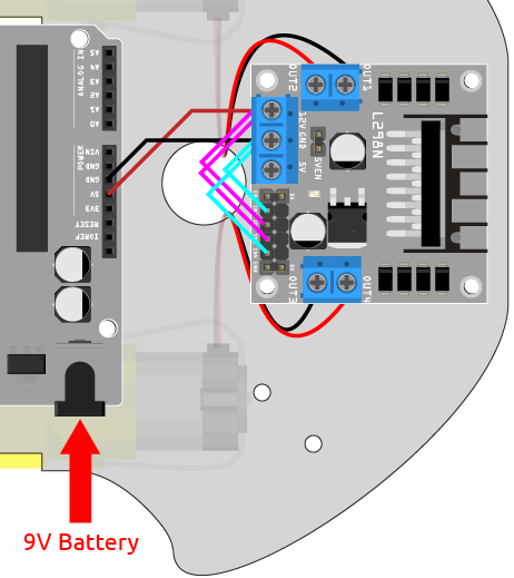
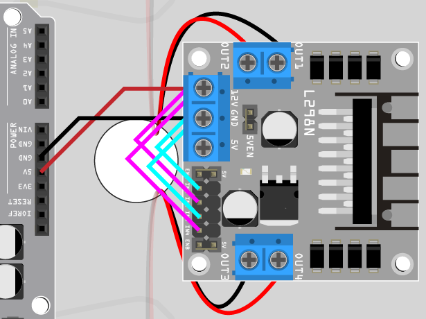
Now let’s connect the input of L298N module directly to 12V and GND respectively to make the car move.
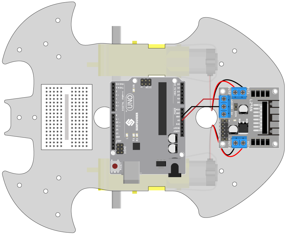
Connect R3 board, L298N module and 2 motors.
L298N |
R3 Board |
Motor |
|---|---|---|
12V |
5V |
|
GND |
GND |
|
OUT1 |
Black wire of right motor |
|
OUT2 |
Red wire of right motor |
|
OUT3 |
Black wire of left motor |
|
OUT4 |
Red wire of left motor |
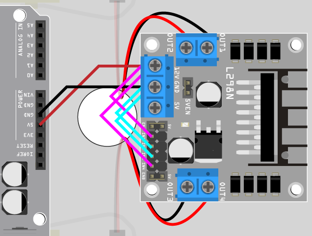
Connect IN2 and IN3 to 12V, and IN1 and IN4 to GND, then you will be able to see the car moving forward.
If not both turn forward, but the following situations occur, you need to readjust the wiring of the two motors.
If both motors turn backward at the same time (left motor turns clockwise, right motor turns counterclockwise), swap the wiring of the left and right motors at the same time, OUT1 and OUT2 swap, OUT3 and OUT4 swap.
If the left motor turns backward (clockwise rotation), exchange the wiring of OUT3 and OUT4 of the left motor.
If the right motor turns backward (counterclockwise rotation), swap the wiring of OUT1 and OUT1 of the right motor.
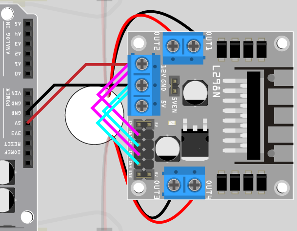
Backward
Connect IN2 and IN3 to GND, and IN1 and IN4 to 12V, then you will be able to see the car moving backward.
Turn Left
If you want to make the car turn left, that is, make both motors turn clockwise. You need to connect IN1 and IN3 to GND, and IN2 and IN4 to 12V.
Turn Right
Conversely, if you want to turn the car to the right, that is, make both motors turn counterclockwise. You need to connect IN1 and IN3 to 12V and IN2 and IN4 to GND.
Stop
To stop the motor, connect the inputs on the same side to 12V or GND at the same time, e.g. connect IN1 and IN2 to 12V or 5V at the same time, and the same for IN3 and IN4.
This is of course theoretical and needed later on when controlling with code. Here remove the power supply to the car can stop it.