4. Follow the line
The car is equipped with a Line Track module, which can be used to make the car follow the black line.
When the line following module detects the black line, the right motor rotates while the left motor does not, so that the car moves one step to the left front. As the car moves, the line module will be moved out of the line, then the left motor turns and the right motor does not turn, the car will move one step to the right to return to the line. Repeat the above two steps, the car can move along the black line.
Before starting the project, you need to build a curve map with black line tape, the recommended line width is between 0.8-1.5cm and the angle of the turn should not be less than 90 degrees.
Required Components
In this project, we need the following components.
It’s definitely convenient to buy a whole kit, here’s the link:
Name |
ITEMS IN THIS KIT |
LINK |
|---|---|---|
3 in 1 Starter Kit |
380+ |
You can also buy them separately from the links below.
COMPONENT INTRODUCTION |
PURCHASE LINK |
|---|---|
- |
|
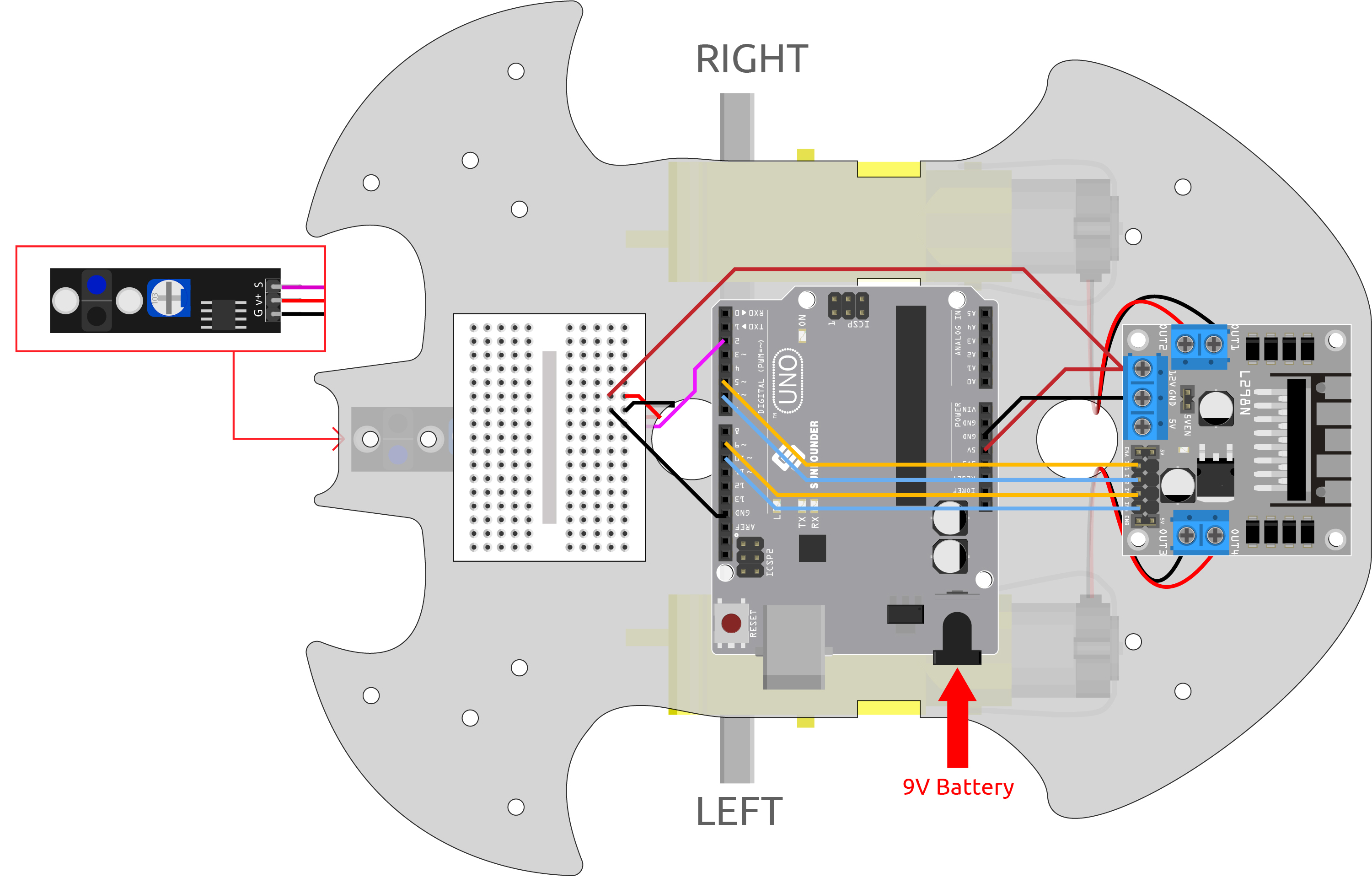
Wiring
This is a digital Line Tracking module, when a black line is detected, it outputs 1; when a white line is detected, it outputs a value of 0. In addition, you can adjust its sensing distance through the potentiometer on the module.
Build the circuit according to the following diagram.
Line Tracking Module |
R3 Board |
|---|---|
S |
2 |
V+ |
5V |
G |
GND |
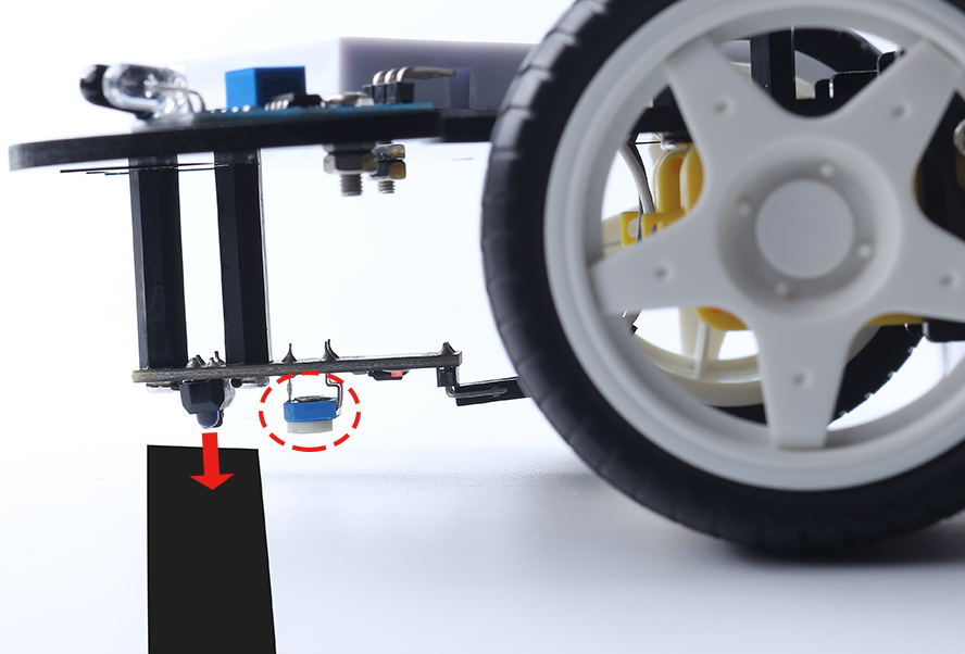
Adjust the Module
Before starting the project, you need to adjust the sensitivity of the module.
Wiring according to the above diagram, then power up the R3 board (either directly into the USB cable or the 9V battery button cable), without uploading the code.
Stick a black electrical tape on the table and put the cart on it.
Observe the signal LED on the module to make sure it lights up on the white table and goes off on the black tape.
If not, you need to adjust the potentiometer on the module, so that it can do the above effect.
Code
Note
Open the
4.follow_the_line.inofile under the path of3in1-kit\car_project\4.follow_the_line.Or copy this code into Arduino IDE.
Or upload the code through the Arduino Web Editor.
After uploading the code to the R3 board, then align the Line Tracking module under the car with the black line, and you will see the car following the line.
How it works?
In this code, it is letting the two motors micro-rotate left and right according to the value of the Line Track module so that you can see the car following the black line.
Add the pin definition for the Line Tracking module, here it is set to
INPUT. Here also initialize the serial monitor and set the baud rate to 9600bps.... const int lineTrack = 2; Serial.begin(9600); void setup() { ... pinMode(lineTrack, INPUT); }
Read the value of the Line Tracking module, if it is 1, then let the car go forward to the left; otherwise go forward to the right. Also you can open the serial monitor by clicking the magnifying glass icon in the upper right corner to see the change of the Line Tracking module value on the black and white line before unplugging the USB cable.
void loop() {

    int speed = 150;

    int lineColor = digitalRead(lineTrack); // 0:white    1:black
    Serial.println(lineColor);
    if (lineColor) {
        moveLeft(speed);
    } else {
        moveRight(speed);
    }
}
About the
moveLeft()andmoveRight()functions.Unlike the left-right turn function in project 2. Move by Code, only small left-right turns are needed here, so you only need to adjust the value of IN2 or IN3 each time. For example, if you move to the left front (
moveLeft()), you only need to set the speed to IN2 and all others to 0, it will make the right motor turn clockwise and the left motor not move.void moveLeft(int speed) { analogWrite(in1, 0); analogWrite(in2, speed); analogWrite(in3, 0); analogWrite(in4, 0); } void moveRight(int speed) { analogWrite(in1, 0); analogWrite(in2, 0); analogWrite(in3, speed); analogWrite(in4, 0); }
-
Used for communication between the Arduino board and a computer or other devices
Serial.begin(): Sets the data rate in bits per second (baud) for serial data transmission.Serial.println(): Prints data to the serial port as human-readable ASCII text followed by a car return character (ASCII 13, or ‘r’) and a newline character (ASCII 10, or ‘n’).
-
The
if elseallows greater control over the flow of code than the basic if statement, by allowing multiple tests to be grouped.