5. Play with Obstacle Avoidance Module
Two infrared obstacle avoidance modules are mounted on the front of the car, which can be used to detect some close obstacles.
In this project, the car is allowed to move forward freely, and when it encounters an obstacle it is able to avoid it and continue to move in other directions.
Required Components
In this project, we need the following components.
It’s definitely convenient to buy a whole kit, here’s the link:
Name |
ITEMS IN THIS KIT |
LINK |
|---|---|---|
3 in 1 Starter Kit |
380+ |
You can also buy them separately from the links below.
COMPONENT INTRODUCTION |
PURCHASE LINK |
|---|---|
- |
|
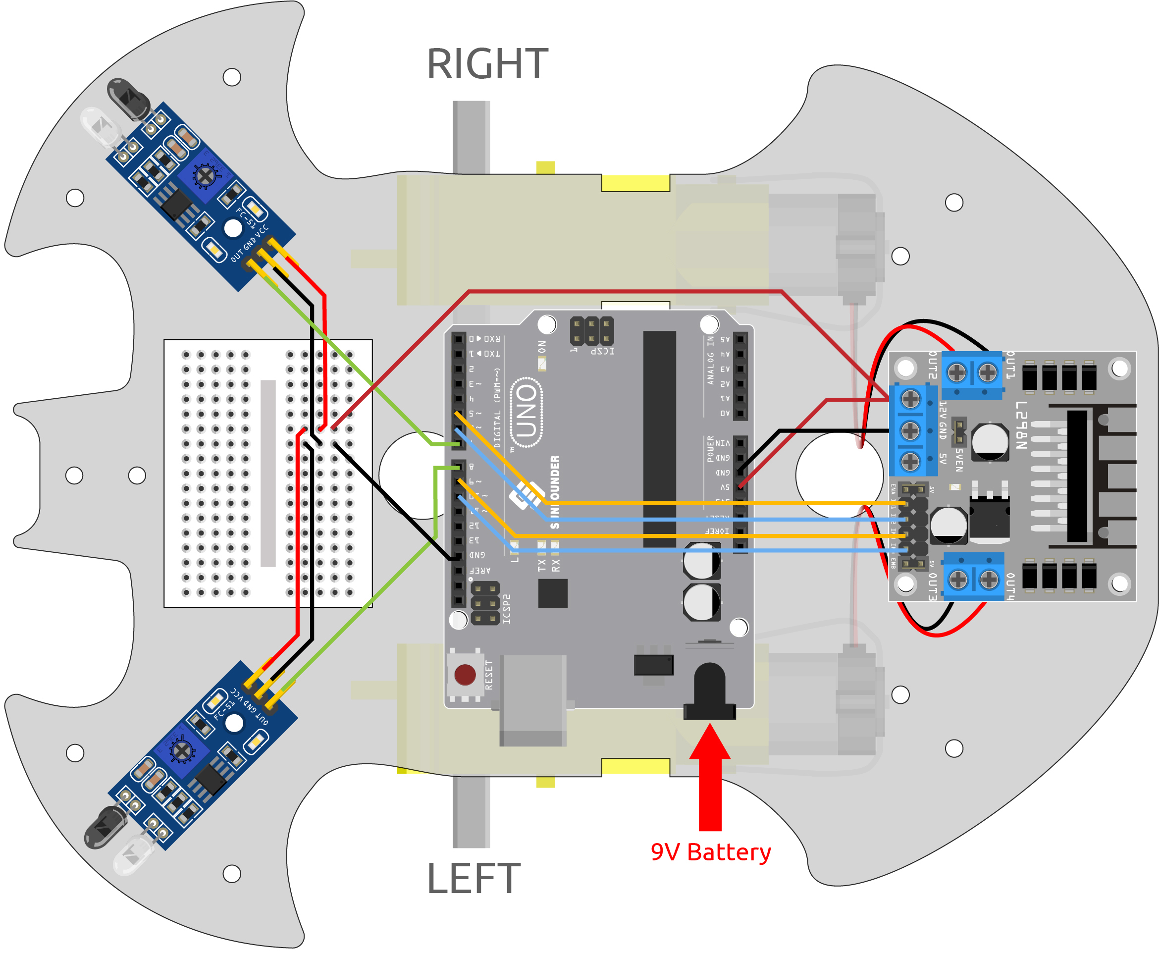
Wiring
The obstacle avoidance module is a distance-adjustable infrared proximity sensor whose output is normally high and low when an obstacle is detected.
Now build the circuit according to the diagram below.
Left IR Module |
R3 Board |
|---|---|
OUT |
8 |
GND |
GND |
VCC |
5V |
Right IR Module |
R3 Board |
|---|---|
OUT |
7 |
GND |
GND |
VCC |
5V |
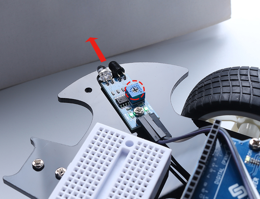
Adjust the Module
Before starting the project, you need to adjust the detection distance of the module.
Wiring according to the above diagram, power up the R3 board (either by plugging in the USB cable directly or by snapping the 9V battery cable), without uploading the code.
Place a notebook or any other flat object about 5cm in front of the IR obstacle avoidance.
Then use a screwdriver to rotate the potentiometer on the module until the signal indicator on the module just lights up, so as to adjust its maximum detection distance of 5cm.
Follow the same method to adjust another infrared module.
Code
Note
Open the
5.obstacle_avoidance_module.inofile under the path of3in1-kit\car_project\5.obstacle_avoidance_module.Or copy this code into Arduino IDE.
Or upload the code through the Arduino Web Editor.
The car will move forward once the code has been successfully uploaded. When the left infrared module detects an obstacle, it will go backwards to the left; when the right infrared module detects an obstacle, it will go backwards to the right; if both sides detect an obstacle, it will go backwards squarely.
How it works?
This project is based on the value of the left and right infrared obstacle avoidance modules to make the car make the appropriate action.
Add the pin definition for the 2 obstacle avoidance modules, here they are set to
INPUT.... const int rightIR = 7; const int leftIR = 8; void setup() { ... //IR obstacle pinMode(leftIR, INPUT); pinMode(rightIR, INPUT); }
Read the values of the left and right infrared modules and let the car to make the corresponding action.
void loop() {

    int left = digitalRead(leftIR);   // 0: Obstructed  1: Empty
    int right = digitalRead(rightIR);
    int speed = 150;

    if (!left && right) {
        backLeft(speed);
    } else if (left && !right) {
        backRight(speed);
    } else if (!left && !right) {
        moveBackward(speed);
    } else {
        moveForward(speed);
    }
}
If the left IR module is 0 (obstacle detected) and the right IR module is 1, let the car back up to the left.
If the right IR module is 0 (obstacle detected), let the car go back up to the right.
If 2 IR modules detect the obstacle at the same time, the car will go backward.
Otherwise the car will keep going forward.
About the
backLeft()function.When the right motor is turning counterclockwise and the left motor is not turning, the car will go backward to the left.
void backLeft(int speed) {
    analogWrite(in1, speed);
    analogWrite(in2, 0);
    analogWrite(in3, 0);
    analogWrite(in4, 0);
}
About the
backLeft()function.When the left motor is turning clockwise and the right motor is not turning, the car will go backward to the right.
void backRight(int speed) {
    analogWrite(in1, 0);
    analogWrite(in2, 0);
    analogWrite(in3, 0);
    analogWrite(in4, speed);
}