Note
Hello, welcome to the SunFounder Raspberry Pi & Arduino & ESP32 Enthusiasts Community on Facebook! Dive deeper into Raspberry Pi, Arduino, and ESP32 with fellow enthusiasts.
Why Join?
Expert Support: Solve post-sale issues and technical challenges with help from our community and team.
Learn & Share: Exchange tips and tutorials to enhance your skills.
Exclusive Previews: Get early access to new product announcements and sneak peeks.
Special Discounts: Enjoy exclusive discounts on our newest products.
Festive Promotions and Giveaways: Take part in giveaways and holiday promotions.
👉 Ready to explore and create with us? Click [here] and join today!
Table Lamp
In the previous projects, we have used the digital input on the Pico. For example, a button can change the pin from low level (off) to high level (on). This is a binary working state.
However, Pico can receive another type of input signal: analog input. It can be in any state from fully closed to fully open, and has a range of possible values. The analog input allows the microcontroller to sense the light intensity, sound intensity, temperature, humidity, etc. of the physical world.
Usually, a microcontroller needs an additional hardware to implement analog input-the analogue-to-digital converter (ADC). But Pico itself has a built-in ADC for us to use directly.
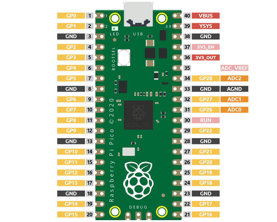
Pico has three GPIO pins that can use analog input, GP26, GP27, GP28. That is, analog channels 0, 1, and 2. In addition, there is a fourth analog channel, which is connected to the built-in temperature sensor and will not be introduced here.
In this project, we try to read the analog value of potentiometer.
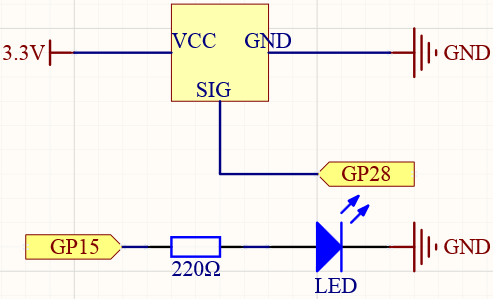
Schematic
Wiring
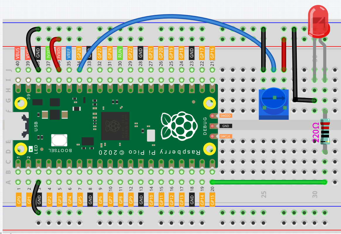
Connect 3V3 and GND of Pico to the power bus of the breadboard.
Insert the potentiometer into the breadboard, its three pins should be in different rows.
Use jumper wires to connect the pins on both sides of the potentiometer to the positive and negative power bus respectively.
Connect the middle pin of the potentiometer to GP28 with a jumper wire.
Connect the anode of the LED to the GP15 pin through a 220Ω resistor, and connect the cathode to the negative power bus.
Code
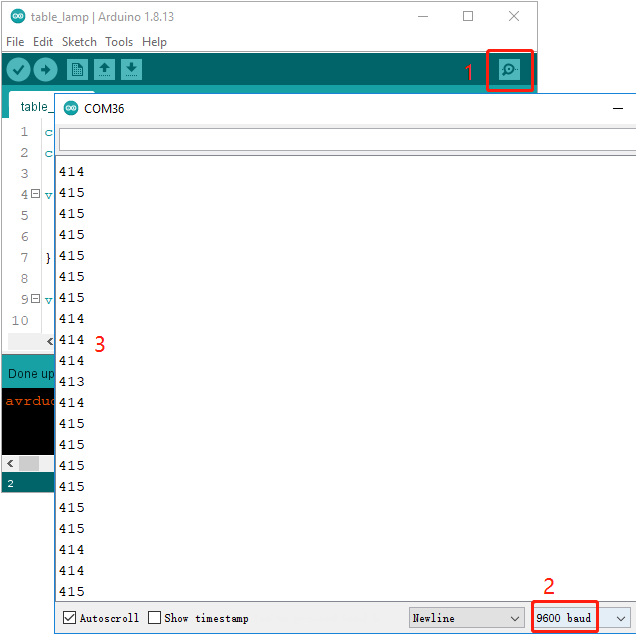
Once the code has been successfully uploaded, open Serial Monitor and then ensure that baudrate is 9600, rotate the potentiometer in 2 directions and you will see that the value range is 0-1023.
When the displayed value is 0, the LED goes off and as the value increases, the LED gets brighter.
Note
If your code is OK and you have selected the correct board and port, but the upload is still not successful.
At this point you can click on the Upload icon again when the progress below shows “Upload…”, unplug the USB cable again and plug it in and the code will be uploaded successfully.
How it works?
To enable Serial Monitor, you need to start serial communication in setup() and set the datarate to 9600.
void setup() {
    pinMode(ledPin, OUTPUT);
    Serial.begin(9600);
}
In the loop function, the value of the potentiometer is read, then the value is mapped from 0-1023 to 0-255 and finally the value after the mapping is used to control the brightness of the LED.
void loop() {
    int sensorValue = analogRead(sensorPin);
    Serial.println(sensorValue);
    int brightness = map(sensorValue, 0, 1023, 0, 255);
    analogWrite(ledPin, brightness);
}
analogRead() is used to read the value of the sensorPin (potentiometer) and assigns it to the variable
sensorValue.
int sensorValue = analogRead(sensorPin);
Print the value of SensorValue in Serial Monitor.
Serial.println(sensorValue);
Here, the map(value, fromLow, fromHigh, toLow, toHigh) function is required as the potentiometer value read is in the range 0-1023 and the value of a PWM pin is in the range 0-255. It is used to Re-maps a number from one range to another. That is, a value of fromLow would get mapped to toLow, a value of fromHigh to toHigh, values in-between to values in-between, etc.
int brightness = map(sensorValue, 0, 1023, 0, 255);
Now we can use this value to control the brightness of the LED.
analogWrite(ledPin,brightness);