Note
Hello, welcome to the SunFounder Raspberry Pi & Arduino & ESP32 Enthusiasts Community on Facebook! Dive deeper into Raspberry Pi, Arduino, and ESP32 with fellow enthusiasts.
Why Join?
Expert Support: Solve post-sale issues and technical challenges with help from our community and team.
Learn & Share: Exchange tips and tutorials to enhance your skills.
Exclusive Previews: Get early access to new product announcements and sneak peeks.
Special Discounts: Enjoy exclusive discounts on our newest products.
Festive Promotions and Giveaways: Take part in giveaways and holiday promotions.
👉 Ready to explore and create with us? Click [here] and join today!
Light Theremin
Theremin is an electronic musical instrument that does not require physical contact. It produces different tones by sensing the position of the player’s hand.
The instrument’s controlling section usually consists of two metal antennas that sense the relative position of the thereminist’s hands and control oscillators for frequency with one hand, and amplitude (volume) with the other. The electric signals from the theremin are amplified and sent to a loudspeaker.
We cannot reproduce the same instrument through Pico, but we can use photoresistor and passive buzzer to achieve similar gameplay.
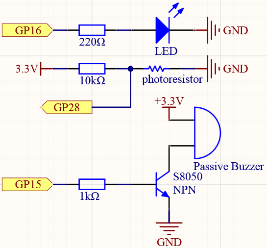
Schematic
Wiring
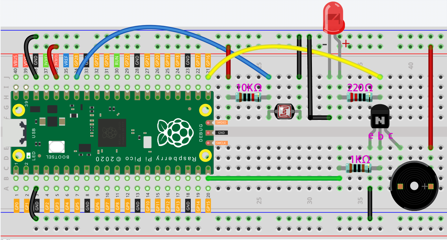
Connect 3V3 and GND of Pico to the power bus of the breadboard.
Connect one lead of the photoresistor to the GP28 pin, then connect the same lead to the positive power bus with a 10K ohm resistor.
Connect another lead of photoresistor to the negative power bus.
Insert the LED into the breadboard, connect its anode pin to the GP16 in series with a 220Ω resistor, and connect its cathode pin to the negative power bus.
Insert the passive buzzer and S8050 transistor into the breadboard. The anode pin of the buzzer is connected to the positive power bus, the cathode pin is connected to the collector lead of the transistor, and the base lead of the transistor is connected to the GP15 pin through a 1kΩ resistor. emitter lead is connected to the negative power bus.
Note
The color ring of the 220Ω resistor is red, red, black, black and brown.
The color ring of the 10kΩ resistor is brown, black, black, red and brown.
Code
When the program runs, the LED will light up, and we will have one seconds to calibrate the detection range of the photoresistor. This is because we may be in a different light environment each time we use it (e.g. the light intensity is different between midday and dusk).
At this time, we need to swing our hands up and down on top of the photoresistor, and the movement range of the hand will be calibrated to the playing range of this instrument.
After one seconds, the LED will go out and we can wave our hands on the photoresistor to play.
How it works?
/* calibrate the photoresistor max & min values */
previousMillis = millis();
digitalWrite(ledPin, HIGH);
while (millis() - previousMillis <= interval) {
  sensorValue = analogRead(photocellPin);
  if (sensorValue > lightHigh) {
    lightHigh = sensorValue;
  }
  if (sensorValue < lightLow) {
    lightLow = sensorValue;
  }
}
digitalWrite(ledPin, LOW);
Set up a calibration process in setup(), using millis() for timing with an interval of 1s (interval = 1000). During this second, wave a hand around the photoresistor, the maximum and minimum values of the detected light are recorded and assigned to lightHigh and lightLow respectively.
sensorValue = analogRead(photocellPin); //read the value of A0
pitch = map(sensorValue, lightLow, lightHigh, 50, 6000);
if (pitch > 50) {
  tone(buzzerPin, pitch, 20);
}
Read the value of the photocell resistor to sensorValue and map it from the small range to the large range to be used to control the frequency of the buzzer. For a detailed explanation of map(), please refer to the course Measure Light Intensity.
tone(buzzerPin, pitch, 20)This function can make the buzzer sound, the frequency is
pitch, and the duration is 20 milliseconds.