Lesson 8 Rotary Encoder
Introduction
A rotary encoder is a type of electro-mechanical device that converts the angular position or motion of a shaft or axle to an analog or digital code. In this lesson, we will learn how to use this device.
Principle
A rotary encoder is an electronic switch with a set of regular pulses with strictly timing sequence. When used with IC, it can achieve increment, decrement, page turning and other operations such as mouse scrolling, menu selection, acoustic sound regulation, frequency regulation, toaster temperature regulation, and so on.
There are mainly two types of rotary encoders: absolute and incremental (relative) encoders. The output of absolute encoders indicates the current position of the shaft, making them angle transducers. The output of incremental encoders provides information about the motion of the shaft, which is typically further processed elsewhere into information such as speed, distance, and position.
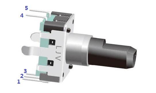
Most rotary encoders have 5 pins with three functions of turning left, turning right and pressing down:
Pin 4 & 5: switching wiring terminals for pressing down (no different from the buttons mentioned previously, so no more details will be provided here.)
Pin 2: generally connected to ground.
Pin 1 & 3: first connected to a pull-up resistor and then to a microprocessor (in this experiment, to GPIO0 and GPIO1 of Raspberry Pi); when you spin the knob of the encoder clockwise and counterclockwise, there will be pulse outputs in pin 1 and pin 3.
If both GPIO0 and GPIO1 are at high level, the switch rotates clockwise; if GPIO0 is at high level but GPIO1 is low, the switch rotates counterclockwise. Therefore, when programming, you only need to check the state of pin 3 when pin 1 is at high level, and then you can tell whether the switch rotates clockwise or counterclockwise.
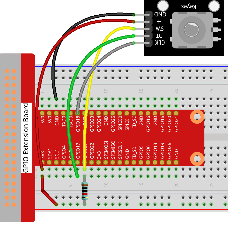
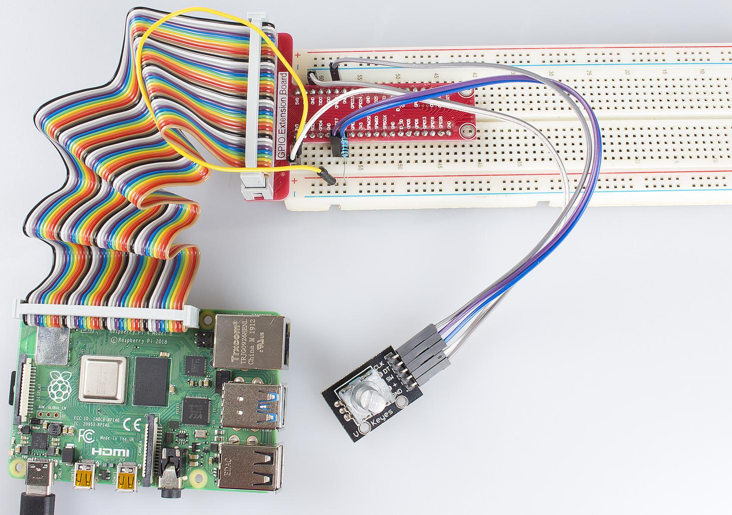
Step 1: Build the circuit.
Raspberry Pi |
Rotary Encoder |
3.3V |
+ |
GND |
GND |
GPIO17 |
DT |
GPIO18 |
CLK |
GPIO27 |
SW |
For C Language Users:
Step 2: Change directory.
cd /home/pi/Sunfounder_SuperKit_C_code_for_RaspberryPi/08_RotaryEncoder/
Step 3: Compile.
gcc rotaryEncoder.c -o rotaryEncoder -lwiringPi
Step 4: Run.
sudo ./rotaryEncoder
Note
If it does not work after running, or there is an error prompt: “wiringPi.h: No such file or directory”, please refer to C code is not working?.
Code
#include <stdio.h>
#include <string.h>
#include <errno.h>
#include <stdlib.h>
#include <wiringPi.h>

#define  RoAPin    0
#define  RoBPin    1
#define  RoSPin    2

static volatile int globalCounter = 0 ;

unsigned char flag;
unsigned char Last_RoB_Status;
unsigned char Current_RoB_Status;

void rotaryDeal(void)
{
    Last_RoB_Status = digitalRead(RoBPin);

    while(!digitalRead(RoAPin)){
        Current_RoB_Status = digitalRead(RoBPin);
        flag = 1;
    }

    if(flag == 1){
        flag = 0;
        if((Last_RoB_Status == 0)&&(Current_RoB_Status == 1)){
            globalCounter ++;
            printf("globalCounter : %d\n",globalCounter);
        }
        if((Last_RoB_Status == 1)&&(Current_RoB_Status == 0)){
            globalCounter --;
            printf("globalCounter : %d\n",globalCounter);
        }

    }
}

void rotaryClear(void)
{
    if(digitalRead(RoSPin) == 0)
    {
        globalCounter = 0;
        printf("globalCounter : %d\n",globalCounter);
        delay(1000);
    }
}

int main(void)
{
    if(wiringPiSetup() < 0){
        fprintf(stderr, "Unable to setup wiringPi:%s\n",strerror(errno));
        return 1;
    }

    pinMode(RoAPin, INPUT);
    pinMode(RoBPin, INPUT);
    pinMode(RoSPin, INPUT);

    pullUpDnControl(RoSPin, PUD_UP);

    while(1){
        rotaryDeal();
        rotaryClear();
    }

    return 0;
}
For Python Users:
Step 2: Change directory.
cd /home/pi/Sunfounder_SuperKit_Python_code_for_RaspberryPi/
Step 3: Run.
sudo python3 08_rotaryEncoder.py
Now, gently rotate the encoder to change the value of the variable in the above program, and you will see the value printed on the screen. Rotate the encoder clockwise, the value will increase; or rotate it counterclockwise, the value will decrease.
Code
import RPi.GPIO as GPIO
import time

# Set up pins
# Rotary A Pin
RoAPin = 17
# Rotary B Pin
RoBPin = 18
# Rotary Switch Pin
RoSPin = 27

def setup():
    global counter
    global Last_RoB_Status, Current_RoB_Status
    GPIO.setmode(GPIO.BCM)
    GPIO.setup(RoAPin, GPIO.IN)
    GPIO.setup(RoBPin, GPIO.IN)
    GPIO.setup(RoSPin,GPIO.IN, pull_up_down=GPIO.PUD_UP)
    # Set up a falling edge detect to callback clear
    GPIO.add_event_detect(RoSPin, GPIO.FALLING, callback=clear)

    # Set up a counter as a global variable
    counter = 0
    Last_RoB_Status = 0
    Current_RoB_Status = 0

# Define a function to deal with rotary encoder
def rotaryDeal():
    global counter
    global Last_RoB_Status, Current_RoB_Status

    flag = 0
    Last_RoB_Status = GPIO.input(RoBPin)
    # When RoAPin level changes
    while(not GPIO.input(RoAPin)):
        Current_RoB_Status = GPIO.input(RoBPin)
        flag = 1
    if flag == 1:
        # Reset flag
        flag = 0
        if (Last_RoB_Status == 0) and (Current_RoB_Status == 1):
            counter = counter + 1
        if (Last_RoB_Status == 1) and (Current_RoB_Status == 0):
            counter = counter - 1
        print ("counter = %d" % counter)

# Define a callback function on switch, to clean "counter"
def clear(ev=None):
    global counter
    counter = 0
    print ("counter = %d" % counter)

def main():
    while True:
        rotaryDeal()

def destroy():
    # Release resource
    GPIO.cleanup()

# If run this script directly, do:
if __name__ == '__main__':
    setup()
    try:
        main()
    # When 'Ctrl+C' is pressed, the child program
    # destroy() will be  executed.
    except KeyboardInterrupt:
        destroy()
Further Exploration
In this experiment, the pressing down function of rotary encoder is not involved. Try to explore this function by yourself!