Lesson 13 LCD1602
Introduction
In this lesson, we will learn how to use LCD1602 to display characters and strings.
Principle
LCD1602, or character type LCD1602, is a dot matrix LCD module specially used to display letters, figures, symbols, and so on. It consists of many 16*2 dot matrixes, and each one is composed of 5*7 or 5*11 character bit. Each character bit can display one character. There is a dot space between each adjacent character bit. Also there is a dot space between each row. The dot space functions as a character space or line space; thus, LCD1602 cannot display graphics very well. It is widely used in pocket instruments and low power application systems due to its micro power consumption, small size, richness in contents, ultra-thinness and lightness.
LCD1602 uses the standard 16-pin port, among which:
Pin 1 (GND): connected to Ground
Pin 2 (Vcc): connected to 5V power supply
Pin 3 (Vo): used to adjust the contrast of LCD1602; the level is lowest when it’s connected to a positive power supply, and highest when connected to ground (you can connect a 10K potentiometer to adjust its contrast when using LCD1602)
Pin 4 (RS): register select pin that controls where in the LCD’s memory you are writing data to. You can select either the data register, which holds what goes on the screen, or an instruction register, which is where the LCD’s controller looks for instructions on what to do next.
Pin 5 (R/W): to read/write signals; it reads signals when supplied with high level (1), and writes when low level (0) (in this experiment, you only need to write data to LCD1602, so just connect this pin to ground)
Pin 6 (E): An enable pin that, when low-level energy is supplied, causes the LCD module to execute relevant instructions
Pin 7 (D0-D7): pins that read and write data
A and K: controlling LCD backlight
LCD1602 has two operation modes: 4-bit and 8-bit. When the IOs of microprocessor (MCU) are insufficient, you can choose 4-bit mode, under which only pins D4~D7 are used. After connecting the circuit, you can operate LCD1602 by Raspberry Pi.
Schematic Diagram
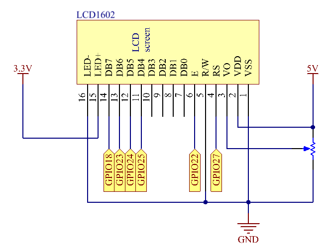
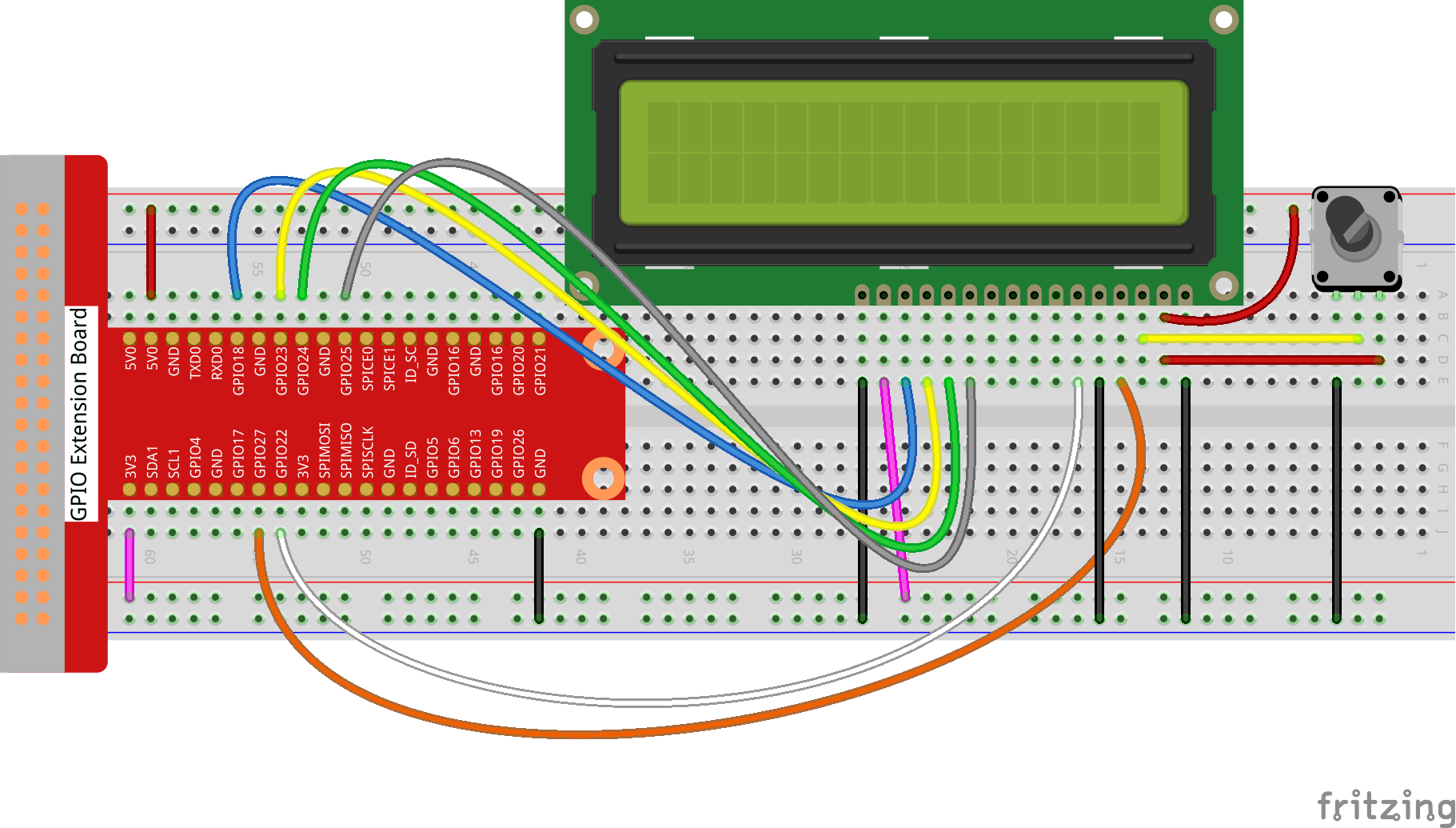
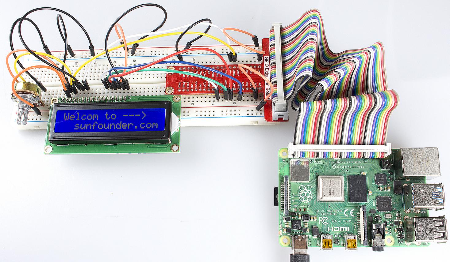
Experimental Procedures
Step1: Build the circuit (please be sure the pins are connected correctly. Otherwise, characters will not be displayed properly):
For C Language Users:
Step 2: Change directory.
cd /home/pi/Sunfounder_SuperKit_C_code_for_RaspberryPi/13_LCD1602/
Step 3: Compile.
gcc lcd1602_2.c -o lcd1602_2 -lwiringPiDev -lwiringPi
Step 4: Run.
sudo ./lcd1602_2
Note
If it does not work after running, or there is an error prompt: “wiringPi.h: No such file or directory”, please refer to C code is not working?.
Code
#include <stdio.h>
#include <stdlib.h>
#include <wiringPi.h>
#include <lcd.h>

const unsigned char Buf[] = "---SUNFOUNDER---";
const unsigned char myBuf[] = "  sunfounder.com";

int main(void)
{
    int fd;
    int i;
    if (wiringPiSetup() == -1){
        exit(1);
    }

    fd = lcdInit(2,16,4, 2,3, 6,5,4,1,0,0,0,0); //see /usr/local/include/lcd.h
    printf("%d", fd);
    if (fd == -1){
        printf("lcdInit 1 failed\n") ;
        return 1;
    }
    delay(1000);

    lcdClear(fd);
    lcdPosition(fd, 0, 0);
    lcdPuts(fd, "Welcom To--->");

    lcdPosition(fd, 0, 1);
    lcdPuts(fd, "  sunfounder.com");

    delay(1000);
    lcdClear(fd);

    while(1){
        for(i=0;i<sizeof(Buf)-1;i++){
            lcdPosition(fd, i, 1);
            lcdPutchar(fd, *(Buf+i));
            delay(200);
        }
        lcdPosition(fd, 0, 1);
        lcdClear(fd);
        delay(500);
        for(i=0; i<16; i++){
            lcdPosition(fd, i, 0);
            lcdPutchar(fd, *(myBuf+i));
            delay(100);
        }
    }

    return 0;
}
For Python Users:
Step 2: Change directory.
cd /home/pi/Sunfounder_SuperKit_Python_code_for_RaspberryPi/
Step 3: Run.
sudo python3 13_lcd1602.py
You should see two lines of characters displayed on the LCD1602: “SUNFOUNDER” and “Hello World ! :)”.
Code
from time import sleep

class LCD:
    # commands
    LCD_CLEARDISPLAY        = 0x01
    LCD_RETURNHOME          = 0x02
    LCD_ENTRYMODESET        = 0x04
    LCD_DISPLAYCONTROL      = 0x08
    LCD_CURSORSHIFT         = 0x10
    LCD_FUNCTIONSET         = 0x20
    LCD_SETCGRAMADDR        = 0x40
    LCD_SETDDRAMADDR        = 0x80

    # flags for display entry mode
    LCD_ENTRYRIGHT      = 0x00
    LCD_ENTRYLEFT       = 0x02
    LCD_ENTRYSHIFTINCREMENT     = 0x01
    LCD_ENTRYSHIFTDECREMENT     = 0x00

    # flags for display on/off control
    LCD_DISPLAYON       = 0x04
    LCD_DISPLAYOFF      = 0x00
    LCD_CURSORON        = 0x02
    LCD_CURSOROFF       = 0x00
    LCD_BLINKON         = 0x01
    LCD_BLINKOFF        = 0x00

    # flags for display/cursor shift
    LCD_DISPLAYMOVE     = 0x08
    LCD_CURSORMOVE      = 0x00

    # flags for display/cursor shift
    LCD_DISPLAYMOVE     = 0x08
    LCD_CURSORMOVE      = 0x00
    LCD_MOVERIGHT       = 0x04
    LCD_MOVELEFT        = 0x00

    # flags for function set
    LCD_8BITMODE        = 0x10
    LCD_4BITMODE        = 0x00
    LCD_2LINE           = 0x08
    LCD_1LINE           = 0x00
    LCD_5x10DOTS        = 0x04
    LCD_5x8DOTS         = 0x00

    def __init__(self, pin_rs=27, pin_e=22, pins_db=[25, 24, 23, 18], GPIO = None):
        # Emulate the old behavior of using RPi.GPIO if we haven't been given
        # an explicit GPIO interface to use
        if not GPIO:
            import RPi.GPIO as GPIO
            self.GPIO = GPIO
            self.pin_rs = pin_rs
            self.pin_e = pin_e
            self.pins_db = pins_db

            self.used_gpio = self.pins_db[:]
            self.used_gpio.append(pin_e)
            self.used_gpio.append(pin_rs)

            self.GPIO.setwarnings(False)
            self.GPIO.setmode(GPIO.BCM)
            self.GPIO.setup(self.pin_e, GPIO.OUT)
            self.GPIO.setup(self.pin_rs, GPIO.OUT)

            for pin in self.pins_db:
                self.GPIO.setup(pin, GPIO.OUT)

        self.write4bits(0x33) # initialization
        self.write4bits(0x32) # initialization
        self.write4bits(0x28) # 2 line 5x7 matrix
        self.write4bits(0x0C) # turn cursor off 0x0E to enable cursor
        self.write4bits(0x06) # shift cursor right

        self.displaycontrol = self.LCD_DISPLAYON | self.LCD_CURSOROFF | self.LCD_BLINKOFF

        self.displayfunction = self.LCD_4BITMODE | self.LCD_1LINE | self.LCD_5x8DOTS
        self.displayfunction |= self.LCD_2LINE

        """ Initialize to default text direction (for romance languages) """
        self.displaymode =  self.LCD_ENTRYLEFT | self.LCD_ENTRYSHIFTDECREMENT
        self.write4bits(self.LCD_ENTRYMODESET | self.displaymode) #  set the entry mode

        self.clear()

    def begin(self, cols, lines):
        if (lines > 1):
            self.numlines = lines
            self.displayfunction |= self.LCD_2LINE
            self.currline = 0

    def home(self):
        self.write4bits(self.LCD_RETURNHOME) # set cursor position to zero
        self.delayMicroseconds(3000) # this command takes a long time!

    def clear(self):
        self.write4bits(self.LCD_CLEARDISPLAY) # command to clear display
        self.delayMicroseconds(3000)    # 3000 microsecond sleep, clearing the display takes a long time

    def setCursor(self, col, row):
        self.row_offsets = [ 0x00, 0x40, 0x14, 0x54 ]

        if ( row > self.numlines ):
            row = self.numlines - 1 # we count rows starting w/0

        self.write4bits(self.LCD_SETDDRAMADDR | (col + self.row_offsets[row]))

    def noDisplay(self):
        # Turn the display off (quickly)
        self.displaycontrol &= ~self.LCD_DISPLAYON
        self.write4bits(self.LCD_DISPLAYCONTROL | self.displaycontrol)

    def display(self):
        # Turn the display on (quickly)
        self.displaycontrol |= self.LCD_DISPLAYON
        self.write4bits(self.LCD_DISPLAYCONTROL | self.displaycontrol)

    def noCursor(self):
        # Turns the underline cursor on/off
        self.displaycontrol &= ~self.LCD_CURSORON
        self.write4bits(self.LCD_DISPLAYCONTROL | self.displaycontrol)

    def cursor(self):
        # Cursor On
        self.displaycontrol |= self.LCD_CURSORON
        self.write4bits(self.LCD_DISPLAYCONTROL | self.displaycontrol)

    def noBlink(self):
        # Turn on and off the blinking cursor
        self.displaycontrol &= ~self.LCD_BLINKON
        self.write4bits(self.LCD_DISPLAYCONTROL | self.displaycontrol)

    def noBlink(self):
        # Turn on and off the blinking cursor
        self.displaycontrol &= ~self.LCD_BLINKON
        self.write4bits(self.LCD_DISPLAYCONTROL | self.displaycontrol)

    def scrollDisplayLeft(self):
        # These commands scroll the display without changing the RAM
        self.write4bits(self.LCD_CURSORSHIFT | self.LCD_DISPLAYMOVE | self.LCD_MOVELEFT)

    def scrollDisplayRight(self):
        # These commands scroll the display without changing the RAM
        self.write4bits(self.LCD_CURSORSHIFT | self.LCD_DISPLAYMOVE | self.LCD_MOVERIGHT);

    def leftToRight(self):
        # This is for text that flows Left to Right
        self.displaymode |= self.LCD_ENTRYLEFT
        self.write4bits(self.LCD_ENTRYMODESET | self.displaymode);

    def rightToLeft(self):
        # This is for text that flows Right to Left
        self.displaymode &= ~self.LCD_ENTRYLEFT
        self.write4bits(self.LCD_ENTRYMODESET | self.displaymode)

    def autoscroll(self):
        # This will 'right justify' text from the cursor
        self.displaymode |= self.LCD_ENTRYSHIFTINCREMENT
        self.write4bits(self.LCD_ENTRYMODESET | self.displaymode)

    def noAutoscroll(self):
        # This will 'left justify' text from the cursor
        self.displaymode &= ~self.LCD_ENTRYSHIFTINCREMENT
        self.write4bits(self.LCD_ENTRYMODESET | self.displaymode)

    def write4bits(self, bits, char_mode=False):
        # Send command to LCD
        self.delayMicroseconds(1000) # 1000 microsecond sleep
        bits=bin(bits)[2:].zfill(8)
        self.GPIO.output(self.pin_rs, char_mode)
        for pin in self.pins_db:
            self.GPIO.output(pin, False)
        for i in range(4):
            if bits[i] == "1":
                self.GPIO.output(self.pins_db[::-1][i], True)
        self.pulseEnable()
        for pin in self.pins_db:
            self.GPIO.output(pin, False)
        for i in range(4,8):
            if bits[i] == "1":
                self.GPIO.output(self.pins_db[::-1][i-4], True)
        self.pulseEnable()

    def delayMicroseconds(self, microseconds):
        seconds = microseconds / float(1000000) # divide microseconds by 1 million for seconds
        sleep(seconds)

    def pulseEnable(self):
        self.GPIO.output(self.pin_e, False)
        self.delayMicroseconds(1)       # 1 microsecond pause - enable pulse must be > 450ns
        self.GPIO.output(self.pin_e, True)
        self.delayMicroseconds(1)       # 1 microsecond pause - enable pulse must be > 450ns
        self.GPIO.output(self.pin_e, False)
        self.delayMicroseconds(1)       # commands need > 37us to settle

    def message(self, text):
        # Send string to LCD. Newline wraps to second line
        print ("message: %s"%text)
        for char in text:
            if char == '\n':
                self.write4bits(0xC0) # next line
            else:
                self.write4bits(ord(char),True)

    def destroy(self):
        #print ("clean up used_gpio")
        self.GPIO.cleanup(self.used_gpio)

def loop():
    global lcd
    lcd = LCD()
    while True:
        lcd.clear()
        lcd.message(" LCD 1602 Test \n123456789ABCDEF")
        sleep(2)
        lcd.clear()
        lcd.message("   SUNFOUNDER \nHello World ! :)")
        sleep(2)
        lcd.clear()
        lcd.message("Welcom to --->\n  sunfounder.com")
        sleep(2)

def destroy():
    lcd.destroy()

if __name__ == '__main__':
    try:
        loop()
    except KeyboardInterrupt:
        destroy()
Further Exploration
In this experiment, the LCD1602 is driven in the 4-bit mode. You can try programming by yourself to drive it in the 8-bit mode.