Lesson 7 How to Drive a DC Motor
Introduction
In this lesson, we will learn to how to use L293D to drive a DC motor and make it rotate clockwise and counterclockwise.
Components
- 1 * Raspberry Pi
- 1 * Breadboard
- 1 * L293D
- 1 * DC motor
- 1 * Power Module
- Jumper wires
Principle
L293D
L293D is a 4-channel motor driver integrated by chip with high voltage and high current. It’s designed to connect to standard DTL, TTL logic level, and drive inductive loads (such as relay coils, DC, Stepper Motors) and power switching transistors etc. DC Motors are devices that turn DC electrical energy into mechanical energy. They are widely used in electrical drive for their superior speed regulation performance.
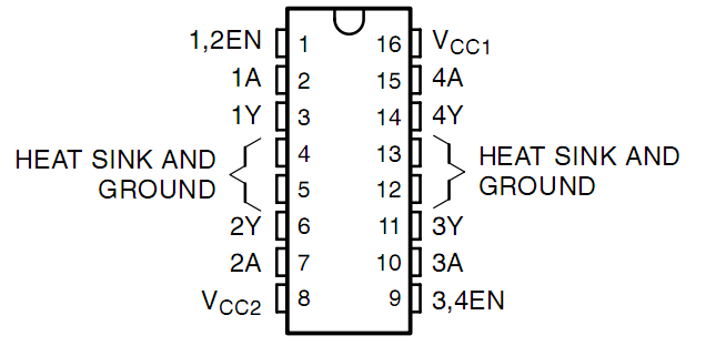
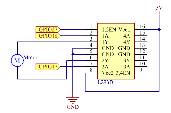
See the figure of pins below. L293D has two pins (Vcc1 and Vcc2) for power supply. Vcc2 is used to supply power for the motor, while Vcc1 to supply for the chip.
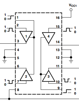
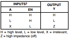
The following is the internal structure of L293D. Pin EN is an enable pin and only works with high level; A stands for input and Y for output. You can see the relationship among them at the right bottom. When pin EN is High level, if A is High, Y outputs high level; if A is Low, Y outputs Low level. When pin EN is Low level, the L293D does not work.
DC Motor
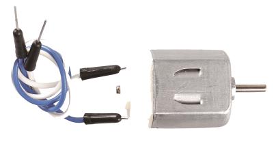
This is a 5V DC motor. It will rotate when you give the two terminals of the copper sheet one high and one low level. For convenience, you can weld the pins to it.
Size: 25*20*15MM
Operation Voltage: 1-6V
Free-run current (3V): 70mA
Free-run speed (3V): 13000RPM
Stall current (3V): 800mA
Shaft diameter: 2mm
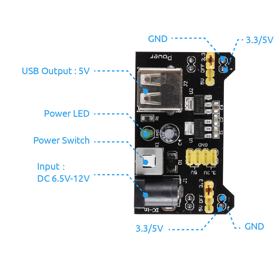
Power Supply Module
In this experiment, it needs large currents to drive the motor especially when it starts and stops, which will severely interfere with the normal work of Raspberry Pi. Therefore, we separately supply power for the motor by this module to make it run safely and steadily.
You can just plug it in the breadboard to supply power. It provides a voltage of 3.3V and 5V, and you can connect either via a jumper cap included.
Schematic Diagram
Plug the power supply module in breadboard, and insert the jumper cap to pin of 5V, then it will output voltage of 5V. Connect pin 1 of L293D to GPIO22, and set it as high level. Connect pin2 to GPIO27, and pin7 to GPIO17, then set one pin high, while the other low. Thus you can change the motor’s rotation direction.
Experimental Procedures
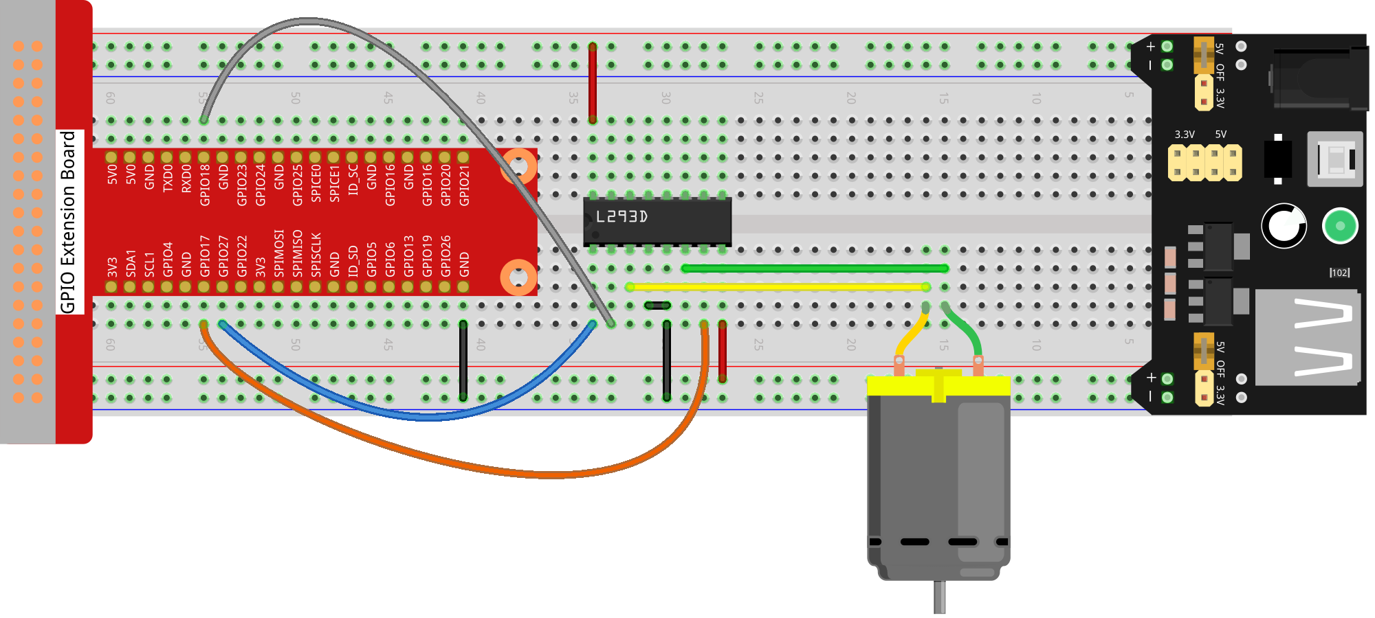
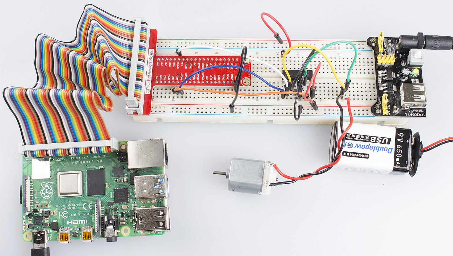
Step 1: Build the circuit.
For C Language Users:
Step 2: Change directory.
cd /home/pi/Sunfounder_SuperKit_C_code_for_RaspberryPi/07_Motor/
Step 3: Compile.
gcc motor.c -o motor -lwiringPi
Step 4: Run.
sudo ./motor
Note
If it does not work after running, or there is an error prompt: “wiringPi.h: No such file or directory”, please refer to C code is not working?.
Code
#include <wiringPi.h>
#include <stdio.h>

#define MotorPin1    0
#define MotorPin2    1
#define MotorEnable  2

int main(void)
{
    if(wiringPiSetup() == -1){ //when initialize wiring failed,print messageto screen
        printf("setup wiringPi failed !");
        return 1;
    }

    pinMode(MotorPin1, OUTPUT);
    pinMode(MotorPin2, OUTPUT);
    pinMode(MotorEnable, OUTPUT);

    int i;

    while(1){
        digitalWrite(MotorEnable, HIGH);
        digitalWrite(MotorPin1, HIGH);
        digitalWrite(MotorPin2, LOW);
        for(i=0;i<3;i++){
            delay(1000);
        }

        digitalWrite(MotorEnable, LOW);
            delay(1000);

        digitalWrite(MotorEnable, HIGH);
        digitalWrite(MotorPin1, LOW);
        digitalWrite(MotorPin2, HIGH);
        for(i=0;i<3;i++){
            delay(1000);
        }

        digitalWrite(MotorEnable, LOW);
                        delay(1000);

    }

    return 0;
}
For Python Users:
Step 2: Change directory.
cd /home/pi/Sunfounder_SuperKit_Python_code_for_RaspberryPi/
Step 3: Run.
sudo python3 07_motor.py
Now, you should see the motor blade rotating.
Code
import RPi.GPIO as GPIO
import time

MotorPin1   = 17
MotorPin2   = 18
MotorEnable = 27

def setup():
    GPIO.setmode(GPIO.BCM)          # Numbers GPIOs by BCM
    GPIO.setup(MotorPin1, GPIO.OUT)   # mode --- output
    GPIO.setup(MotorPin2, GPIO.OUT)
    GPIO.setup(MotorEnable, GPIO.OUT)
    GPIO.output(MotorEnable, GPIO.LOW) # motor stop

def loop():
    while True:
        print ("Press Ctrl+C to end the program...")
        GPIO.output(MotorEnable, GPIO.HIGH) # motor driver enable
        GPIO.output(MotorPin1, GPIO.HIGH)  # clockwise
        GPIO.output(MotorPin2, GPIO.LOW)
        time.sleep(5)

        GPIO.output(MotorEnable, GPIO.LOW) # motor stop
        time.sleep(5)

        GPIO.output(MotorEnable, GPIO.HIGH) # motor driver enable
        GPIO.output(MotorPin1, GPIO.LOW)   # anticlockwise
        GPIO.output(MotorPin2, GPIO.HIGH)
        time.sleep(5)

        GPIO.output(MotorEnable, GPIO.LOW) # motor stop
        time.sleep(5)

def destroy():
    GPIO.output(MotorEnable, GPIO.LOW) # motor stop
    GPIO.cleanup()                     # Release resource

if __name__ == '__main__':     # Program start from here
    setup()
    try:
        loop()
    except KeyboardInterrupt:  # When 'Ctrl+C' is pressed, the child program destroy() will be  executed.
        destroy()
Further Exploration
You can use buttons to control the clockwise and counterclockwise rotation of the motor blade based on the previous lessons. Also you can apply the PWM technology to control the rotation.
Summary
Through this lesson, you have learnt the relative principle and driving mode of DC motors, as well as how to drive a motor by Raspberry Pi. You should also pay special attention to the fact that a DC motor will greatly interfere with the whole circuit when it works, so you need to adopt photoelectric isolation and provide separate power supply. A freewheeling diode is also necessary for the whole system to work reliably and steadily.