Lesson 5 RGB LED
Introduction
Previously we’ve used the PWM technology to control an LED brighten and dim. In this lesson, we will use it to control an RGB LED to flash various kinds of colors.
Components
- 1 * Raspberry Pi
- 1 * Breadboard
- 1 * RGB LED
- 3 * Resistor (220Ω)
- Several jumper wires
Principle
RGB
RGB LEDs emit light in various colors. RGB stands for the red, green, and blue color channels and is an industry color standard. They package three LEDs of red, green, and blue into a transparent or semitransparent plastic shell and have four pins. An RGB LED can display various new colors by changing the three channels and superimposing them, which, according to statistics, can create 16,777,216 different colors.
The three primary colors can be mixed into various colors by brightness. The brightness of LED can be adjusted with PWM. Raspberry Pi has only one channel for hardware PWM output, but it needs three channels to control the RGB LED, which means it is difficult to control the RGB LED with the hardware PWM of Raspberry Pi. Fortunately, the softPwm library simulates PWM (softPwm) by programming. You only need to include the header file softPwm.h (for C language users), and then call the API it provides to easily control the RGB LED by multi-channel PWM output, so as to display all kinds of color.
RGB LEDs can be categorized into common anode and common cathode ones. In this experiment, the latter is used.
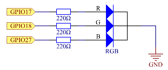
Schematic Diagram
Experimental Procedures
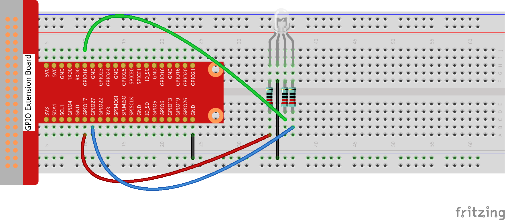
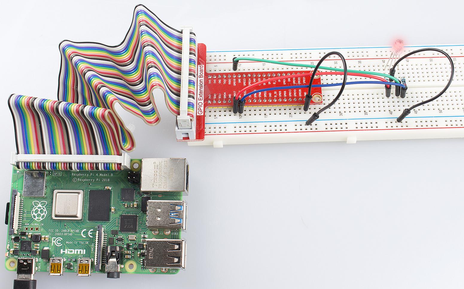
Step 1: Build the circuit.
For C Language Users:
Step 2: Change directory.
cd /home/pi/Sunfounder_SuperKit_C_code_for_RaspberryPi/05_RGB/
Step 3: Compile.
gcc rgb.c -o rgb -lwiringPi -lpthread
Step 4: Run.
sudo ./rgb
Note
If it does not work after running, or there is an error prompt: “wiringPi.h: No such file or directory”, please refer to C code is not working?.
Code
#include <wiringPi.h>
#include <softPwm.h>
#include <stdio.h>

#define uchar unsigned char

#define LedPinRed    0
#define LedPinGreen  1
#define LedPinBlue   2

void ledInit(void)
{
    softPwmCreate(LedPinRed,  0, 100);
    softPwmCreate(LedPinGreen,0, 100);
    softPwmCreate(LedPinBlue, 0, 100);
}

void ledColorSet(uchar r_val, uchar g_val, uchar b_val)
{
    softPwmWrite(LedPinRed,   r_val);
    softPwmWrite(LedPinGreen, g_val);
    softPwmWrite(LedPinBlue,  b_val);
}

int main(void)
{
    int i;

    if(wiringPiSetup() == -1){ //when initialize wiring failed,print messageto screen
        printf("setup wiringPi failed !");
        return 1;
    }
    //printf("linker LedPin : GPIO %d(wiringPi pin)\n",LedPin); //when initialize wiring successfully,print message to screen

    ledInit();

    while(1){
        ledColorSet(0xff,0x00,0x00);   //red
        delay(500);
        ledColorSet(0x00,0xff,0x00);   //green
        delay(500);
        ledColorSet(0x00,0x00,0xff);   //blue
        delay(500);

        ledColorSet(0xff,0xff,0x00);   //yellow
        delay(500);
        ledColorSet(0xff,0x00,0xff);   //pick
        delay(500);
        ledColorSet(0xc0,0xff,0x3e);
        delay(500);

        ledColorSet(0x94,0x00,0xd3);
        delay(500);
        ledColorSet(0x76,0xee,0x00);
        delay(500);
        ledColorSet(0x00,0xc5,0xcd);
        delay(500);

    }

    return 0;
}
For Python Users:
Step 2: Change directory.
cd /home/pi/Sunfounder_SuperKit_Python_code_for_RaspberryPi/
Step 3: Run.
sudo python3 05_rgb.py
Here you should see the RGB LED flash different colors in turn.
Code
import RPi.GPIO as GPIO
import time

colors = [0xFF0000, 0x00FF00, 0x0000FF, 0xFFFF00, 0xFF00FF, 0x00FFFF]
pins = {'pin_R':17, 'pin_G':18, 'pin_B':27}  # pins is a dict

GPIO.setmode(GPIO.BCM)       # Numbers GPIOs by BCM
for i in pins:
    GPIO.setup(pins[i], GPIO.OUT)   # Set pins' mode is output
    GPIO.output(pins[i], GPIO.HIGH) # Set pins to high(+3.3V) to off led

p_R = GPIO.PWM(pins['pin_R'], 2000)  # set Frequece to 2KHz
p_G = GPIO.PWM(pins['pin_G'], 2000)
p_B = GPIO.PWM(pins['pin_B'], 5000)

p_R.start(0)      # Initial duty Cycle = 0(leds off)
p_G.start(0)
p_B.start(0)

def map(x, in_min, in_max, out_min, out_max):
    return (x - in_min) * (out_max - out_min) / (in_max - in_min) + out_min

def setColor(col):   # For example : col = 0x112233
    R_val = (col & 0xFF0000) >> 16
    G_val = (col & 0x00FF00) >> 8
    B_val = (col & 0x0000FF) >> 0

    R_val = map(R_val, 0, 255, 0, 100)
    G_val = map(G_val, 0, 255, 0, 100)
    B_val = map(B_val, 0, 255, 0, 100)

    p_R.ChangeDutyCycle(R_val)     # Change duty cycle
    p_G.ChangeDutyCycle(G_val)
    p_B.ChangeDutyCycle(B_val)

try:
    while True:
        for col in colors:
            setColor(col)
            time.sleep(0.5)
except KeyboardInterrupt:
    p_R.stop()
    p_G.stop()
    p_B.stop()
    for i in pins:
        GPIO.output(pins[i], GPIO.HIGH)    # Turn off all leds
    GPIO.cleanup()
Further Exploration
You can modify the parameters of the function ledColorSet( ) by yourself, and then compile and run the code to see the color changes of the RGB LED.
Experimental Summary
In this experiment, you have learnt how to control RGB LEDs with the softPwm of Raspberry Pi in this experiment. Try to apply the softPwm to DC motor speed regulation.