Lesson 12 Driving Dot-Matrix by 74HC595
Introduction
With low-voltage scanning, dot matrix LED displays have advantages such as power saving, long service life, low cost, high brightness, a wide angle of view, long visual range, waterproofness, and so on. They can meet the needs of different applications and thus have a broad development prospect. In this lesson, we will learn how to use 74HC595 to drive an LED dot-matrix.
Principle
Dot Matrix
The external view:
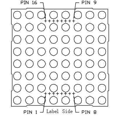
Pin definition:
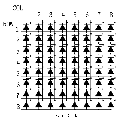
Define the row and column numbering at first (only for the dot matrix whose model number ends with BS)
Pin numbering corresponding to the above rows and columns:
COL |
1 |
2 |
3 |
4 |
5 |
6 |
7 |
8 |
Pin No. |
13 |
3 |
4 |
10 |
6 |
11 |
15 |
16 |
ROW |
1 |
2 |
3 |
4 |
5 |
6 |
7 |
8 |
Pin No. |
9 |
14 |
8 |
12 |
1 |
7 |
2 |
5 |
The 8*8 dot matrix is made up of sixty-four LEDs and each LED is placed at the cross point of a row and a column. When the electrical level of a certain row is High and the electrical level of a certain column is Low, the corresponding LED at their cross point will light up. For example, to turn on the LED at the first dot, you should set ROW 1 to high level and COL 1 to low, so the LED at the first dot brightens; to turn on all the LEDs on the first row, set ROW 1 to high level and COL 1-8 to low, and then all the LEDs on the first row will light up; similarly, set COL 1 to low level and ROW 1-8 to high level, and all the LEDs on the first column will light up.
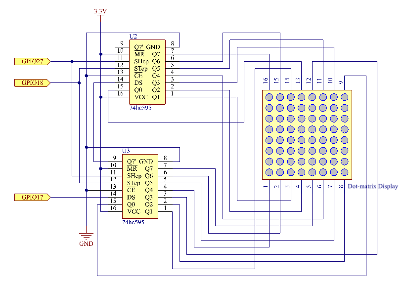
The principle of 74HC595 has been illustrated previously. One chip is used to control the rows of the dot matrix while the other, the columns.
Schematic Diagram
Experimental Procedures
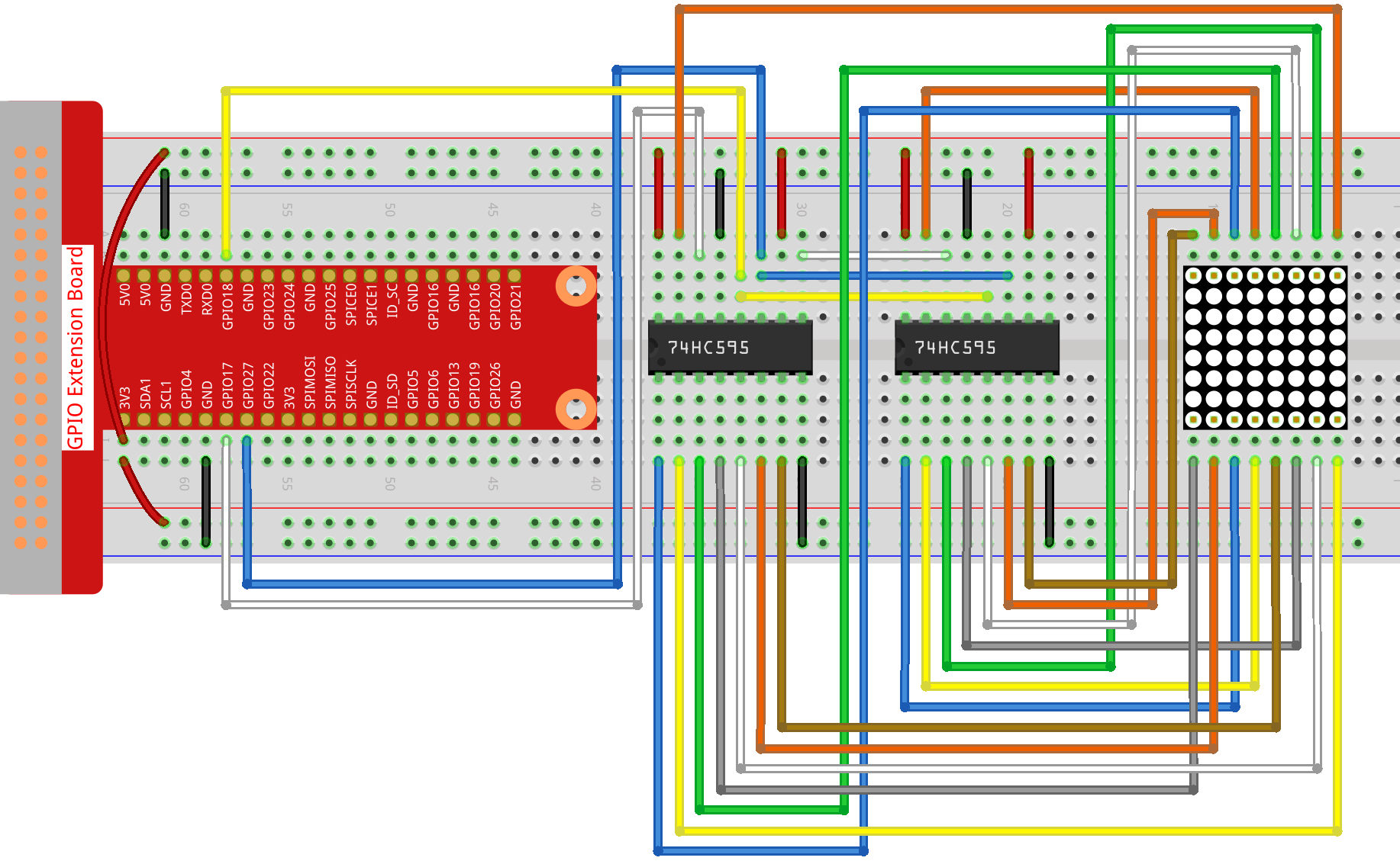
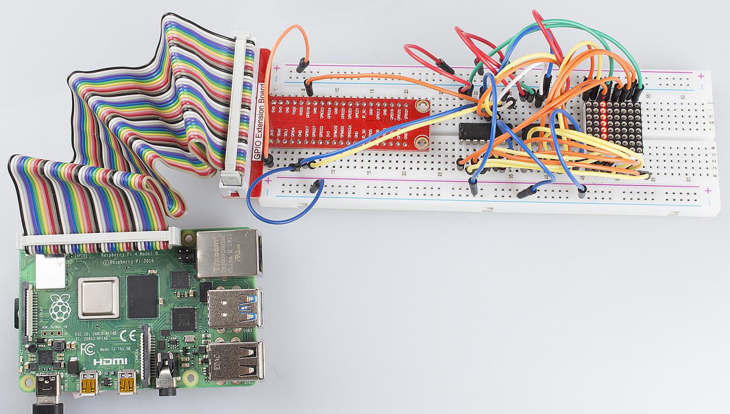
Step 1: Build the circuit.
For C Language Users:
Step 2: Change directory.
cd /home/pi/Sunfounder_SuperKit_C_code_for_RaspberryPi/12_DotMatrix/
Step 3: Compile.
gcc dotMatrix.c -o dotMatrix -lwiringPi
Step 4: Run.
sudo ./dotMatrix
Note
If it does not work after running, or there is an error prompt: “wiringPi.h: No such file or directory”, please refer to C code is not working?.
Code
#include <wiringPi.h>
#include <stdio.h>

#define   SDI   0   //serial data input
#define   RCLK  1   //memory clock input(STCP)
#define   SRCLK 2   //shift register clock input(SHCP)

unsigned char code_H[20] = {0x01,0xff,0x80,0xff,0x01,0x02,0x04,0x08,0x10,0x20,0x40,0x80,0xff,0xff,0xff,0xff,0xff,0xff,0xff,0xff};
unsigned char code_L[20] = {0x00,0x7f,0x00,0xfe,0x00,0x00,0x00,0x00,0x00,0x00,0x00,0x00,0xfe,0xfd,0xfb,0xf7,0xef,0xdf,0xbf,0x7f};

//unsigned char code_L[8] = {0x00,0x00,0x3c,0x42,0x42,0x3c,0x00,0x00};
//unsigned char code_H[8] = {0xff,0xe7,0xdb,0xdb,0xdb,0xdb,0xe7,0xff};

//unsigned char code_L[8] = {0xff,0xff,0xc3,0xbd,0xbd,0xc3,0xff,0xff};
//unsigned char code_H[8] = {0x00,0x18,0x24,0x24,0x24,0x24,0x18,0x00};

void init(void)
{
    pinMode(SDI, OUTPUT); //make P0 output
    pinMode(RCLK, OUTPUT); //make P0 output
    pinMode(SRCLK, OUTPUT); //make P0 output

    digitalWrite(SDI, 0);
    digitalWrite(RCLK, 0);
    digitalWrite(SRCLK, 0);
}

void hc595_in(unsigned char dat)
{
    int i;

    for(i=0;i<8;i++){
        digitalWrite(SDI, 0x80 & (dat << i));
        digitalWrite(SRCLK, 1);
        delay(1);
        digitalWrite(SRCLK, 0);
    }
}

void hc595_out()
{
    digitalWrite(RCLK, 1);
    delay(1);
    digitalWrite(RCLK, 0);
}

int main(void)
{
    int i;

    if(wiringPiSetup() == -1){ //when initialize wiring failed,print messageto screen
        printf("setup wiringPi failed !");
        return 1;
    }

    init();

    while(1){
        for(i=0;i<sizeof(code_H);i++){
            hc595_in(code_L[i]);
            hc595_in(code_H[i]);
            hc595_out();
            delay(100);
        }

        for(i=sizeof(code_H);i>=0;i--){
            hc595_in(code_L[i]);
            hc595_in(code_H[i]);
            hc595_out();
            delay(100);
        }
    }

    return 0;
}
For Python Users:
Step 2: Change directory.
cd /home/pi/Sunfounder_SuperKit_Python_code_for_RaspberryPi/
Step 3: Run.
sudo python3 12_dotMatrix.py
You should see LEDs light up as you control.
Code
import RPi.GPIO as GPIO
import time

SDI   = 17
RCLK  = 18
SRCLK = 27

code_H = [0x01,0xff,0x80,0xff,0x01,0x02,0x04,0x08,0x10,0x20,0x40,0x80,0xff,0xff,0xff,0xff,0xff,0xff,0xff,0xff]
code_L = [0x00,0x7f,0x00,0xfe,0x00,0x00,0x00,0x00,0x00,0x00,0x00,0x00,0xfe,0xfd,0xfb,0xf7,0xef,0xdf,0xbf,0x7f]


def print_msg():
    print ("Program is running...")
    print ("Please press Ctrl+C to end the program...")

def setup():
    GPIO.setmode(GPIO.BCM)    # Number GPIOs by BCM
    GPIO.setup(SDI, GPIO.OUT)
    GPIO.setup(RCLK, GPIO.OUT)
    GPIO.setup(SRCLK, GPIO.OUT)
    GPIO.output(SDI, GPIO.LOW)
    GPIO.output(RCLK, GPIO.LOW)
    GPIO.output(SRCLK, GPIO.LOW)

def hc595_in(dat):
    for bit in range(0, 8):
        GPIO.output(SDI, 0x80 & (dat << bit))
        GPIO.output(SRCLK, GPIO.HIGH)
        time.sleep(0.001)
        GPIO.output(SRCLK, GPIO.LOW)

def hc595_out():
    GPIO.output(RCLK, GPIO.HIGH)
    time.sleep(0.001)
    GPIO.output(RCLK, GPIO.LOW)


def loop():
    while True:
        for i in range(0, len(code_H)):
            hc595_in(code_L[i])
            hc595_in(code_H[i])
            hc595_out()
            time.sleep(0.1)

        for i in range(len(code_H)-1, -1, -1):
            hc595_in(code_L[i])
            hc595_in(code_H[i])
            hc595_out()
            time.sleep(0.1)

def destroy():   # When program ending, the function is executed.
    GPIO.cleanup()

if __name__ == '__main__':   # Program starting from here
    print_msg()
    setup()
    try:
        loop()
    except KeyboardInterrupt:
        destroy()
Summary
Through this lesson, you have got the basic principle of LED dot matrix and how to program the Raspberry Pi to drive an LED dot matrix based on 74HC595 cascade. With the knowledge learnt, try more fascinating creations!