Note
Hello, welcome to the SunFounder Raspberry Pi & Arduino & ESP32 Enthusiasts Community on Facebook! Dive deeper into Raspberry Pi, Arduino, and ESP32 with fellow enthusiasts.
Why Join?
Expert Support: Solve post-sale issues and technical challenges with help from our community and team.
Learn & Share: Exchange tips and tutorials to enhance your skills.
Exclusive Previews: Get early access to new product announcements and sneak peeks.
Special Discounts: Enjoy exclusive discounts on our newest products.
Festive Promotions and Giveaways: Take part in giveaways and holiday promotions.
👉 Ready to explore and create with us? Click [here] and join today!
2.3 - Fading LED
So far, we have used only two output signals: high level and low level (or called 1 & 0, ON & OFF), which is called digital output. However, in actual use, many devices do not simply ON/OFF to work, for example, adjusting the speed of the motor, adjusting the brightness of the desk lamp, and so on. In the past, a slider that can adjust the resistance was used to achieve this goal, but this is always unreliable and inefficient. Therefore, Pulse width modulation (PWM) has emerged as a feasible solution to such complex problems.
A digital output composed of a high level and a low level is called a pulse. The pulse width of these pins can be adjusted by changing the ON/OFF speed.
Simply put, when we are in a short period (such as 20ms, most people’s visual retention time), Let the LED turn on, turn off, and turn on again, we won’t see it has been turned off, but the brightness of the light will be slightly weaker. During this period, the more time the LED is turned on, the higher the brightness of the LED. In other words, in the cycle, the wider the pulse, the greater the “electric signal strength” output by the microcontroller. This is how PWM controls LED brightness (or motor speed).
There are some points to pay attention to when Pico uses PWM. Let’s take a look at this picture.
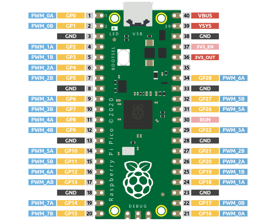
Each GPIO pin of Pico supports PWM, but it actually has a total of 16 independent PWM outputs (instead of 30), distributed between GP0 to GP15 on the left, and the PWM output of the right GPIO is equivalent to the left copy.
What we need to pay attention to is to avoid setting the same PWM channel for different purposes during programming. (For example, GP0 and GP16 are both PWM_0A)
After understanding this knowledge, let us try to achieve the effect of Fading LED.
Schematic
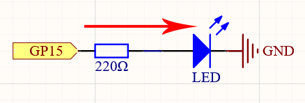
This project is the same circuit as the first project 2.1 - Hello, LED!, but the signal type is different. The first project is to output digital high and low levels (0&1) directly from GP15 to make the LEDs light up or turn off, this project is to output PWM signal from GP15 to control the brightness of the LED.
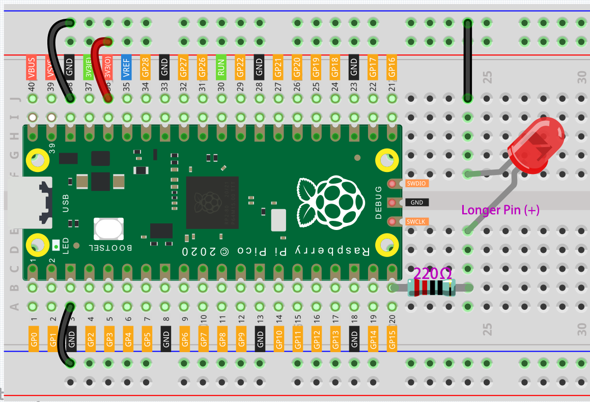
Wiring
Code
Note
You can open the file
2.3_fading_led.inounder the path ofeuler-kit/arduino/2.3_fading_led.Or copy this code into Arduino IDE.
Then select the Raspberry Pi Pico board and the correct port before clicking the Upload button.
The LED will gradually become brighter as the program runs.
How it works?
Declare pin 15 as ledPin.
const int ledPin = 15;
analogWrite() in loop() assigns ledPin an analog value (PWM wave) between 0 and 255 to change the brightness of LED.
analogWrite(ledPin, value);
Using a for loop, the value of analogWrite() can be changed step by step between the minimum value (0) and the maximum value (255).
for (int value = 0 ; value <= 255; value += 5) {
    analogWrite(ledPin, value);
}
In order to see the experimental phenomenon clearly, a delay(30) needs to be added to the for cycle to control the brightness change time.
for (int value = 0 ; value <= 255; value += 5) {
    analogWrite(ledPin, value);
    delay(30);
}