注釈
こんにちは、SunFounderのRaspberry Pi & Arduino & ESP32愛好家コミュニティへようこそ!Facebook上でRaspberry Pi、Arduino、ESP32についてもっと深く掘り下げ、他の愛好家と交流しましょう。
参加する理由は?
エキスパートサポート:コミュニティやチームの助けを借りて、販売後の問題や技術的な課題を解決します。
学び&共有:ヒントやチュートリアルを交換してスキルを向上させましょう。
独占的なプレビュー:新製品の発表や先行プレビューに早期アクセスしましょう。
特別割引:最新製品の独占割引をお楽しみください。
祭りのプロモーションとギフト:ギフトや祝日のプロモーションに参加しましょう。
👉 私たちと一緒に探索し、創造する準備はできていますか?[ここ]をクリックして今すぐ参加しましょう!
1.3.1 モーター
前書き
このレッスンでは、L293Dを使用してDCモーターを駆動し、時計回りと反時計回りに回転させる方法を学習する。 安全上の理由で、DCモーターは大電流を必要とするため、ここでは電源モジュールを使用してモーターに電力を供給する。
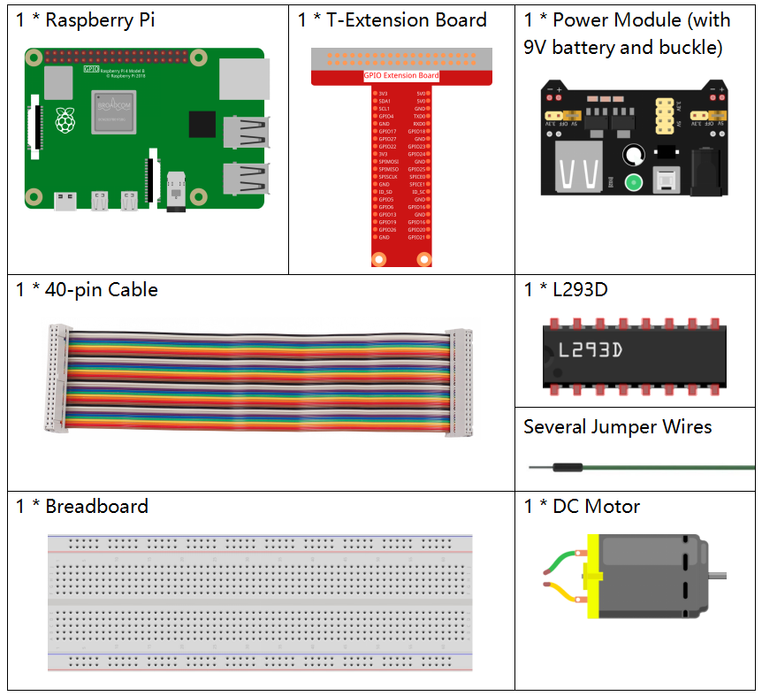
部品
原理
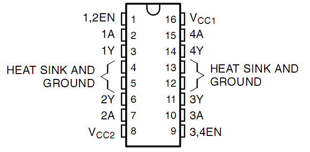
L293D
L293Dは、高電圧と高電流のチップで統合された4チャネルモータードライバーである。 標準のDTL、TTLロジックレベルに接続し、誘導負荷(リレーコイル、DC、ステッピングモーターなど)およびパワースイッチングトランジスタなどを駆動するように設計される。 DCモーターは、DC電気エネルギーを機械エネルギーに変換するデバイスである。それらは、優れた速度調整性能の利点により、電気駆動装置で広く使用されている。
ピンの図については、以下の図を参照してください。L293Dには、電源用の2つのピン(Vcc1とVcc2)がある。Vcc2はモーターに電力を供給し、Vcc1はチップに電力を供給するために使用される。 ここでは小型のDCモーターが使用されているため、両方のピンを+ 5Vに接続してください。
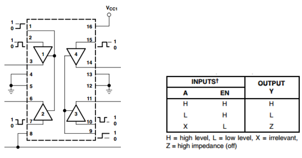
以下はL293Dの内部構造である。ピンENはイネーブルピンであり、高レベルでのみ機能する。Aは入力を表し、Yは出力を表す。それらの間の関係は右下に見ることができる。 ピンENがHighレベルのとき、AがHighの場合、YはHighレベルを出力する。AがLowの場合、YはLowレベルを出力する。ピンENがLowレベルの場合、L293Dは機能しない。
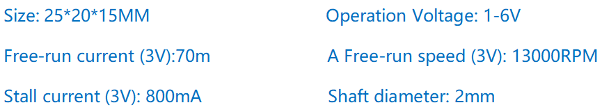
DCモーター
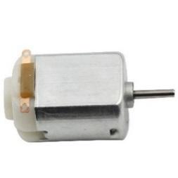
これは5V DCモーターである。銅板の2つの端子に1つの高レベルと1つの低レベルを与えると回転する。便宜上、ピンを溶接することができる。
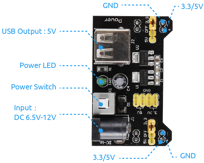
電源モジュール
この実験では、特に起動時と停止時にモーターを駆動するために大きな電流が必要である。 これは、Raspberry Piの通常の動作を大幅に妨害する可能性がある。そのため、このモジュールによってモーターに個別に電力を供給し、安全かつ着実に動作させる。
ブレッドボードに差し込むだけで電力を供給できる。3.3Vと5Vの電圧を提供し、付属のジャンパーキャップを介してどちらでも接続できる。
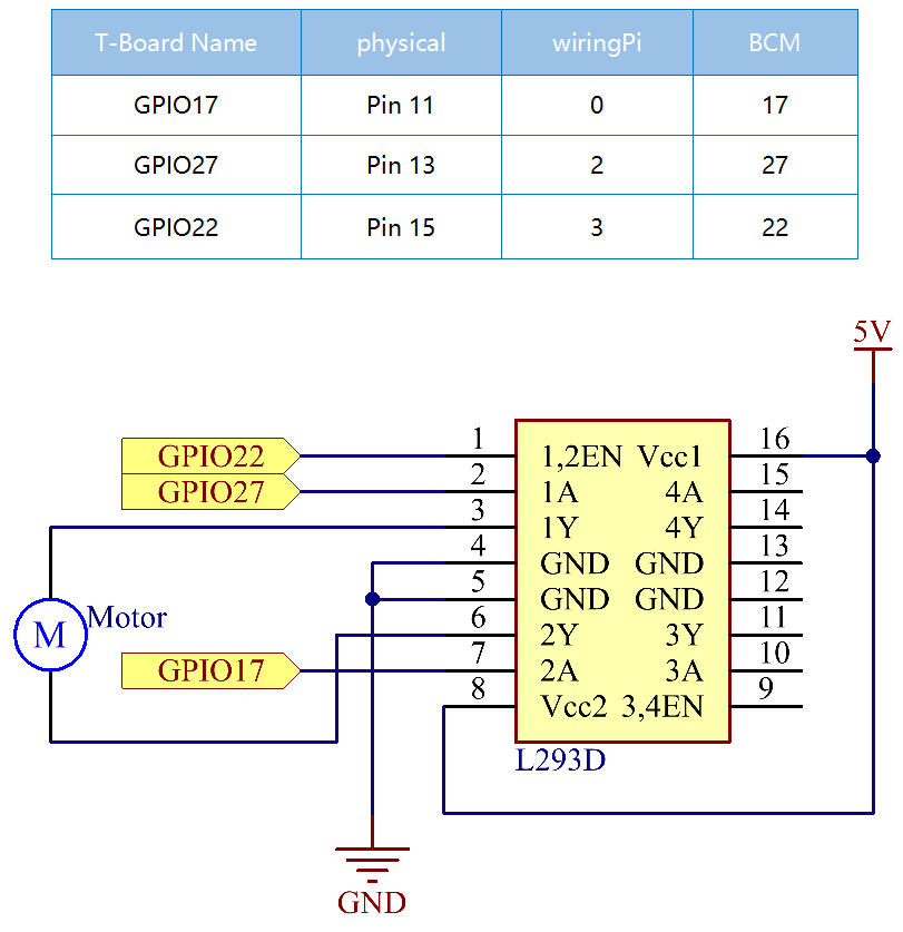
回路図
電源モジュールをブレッドボードに差し込み、ジャンパーキャップを5Vのピンに挿入すると、5Vの電圧が出力される。L293Dのピン1をGPIO22に接続し、それを高レベルに設定する。 ピン2をGPIO27に、ピン7をGPIO17に接続し、一方のピンをhighに、もう一方のピンをhighに設定する。したがって、モーターの回転方向を変更できる。
実験手順
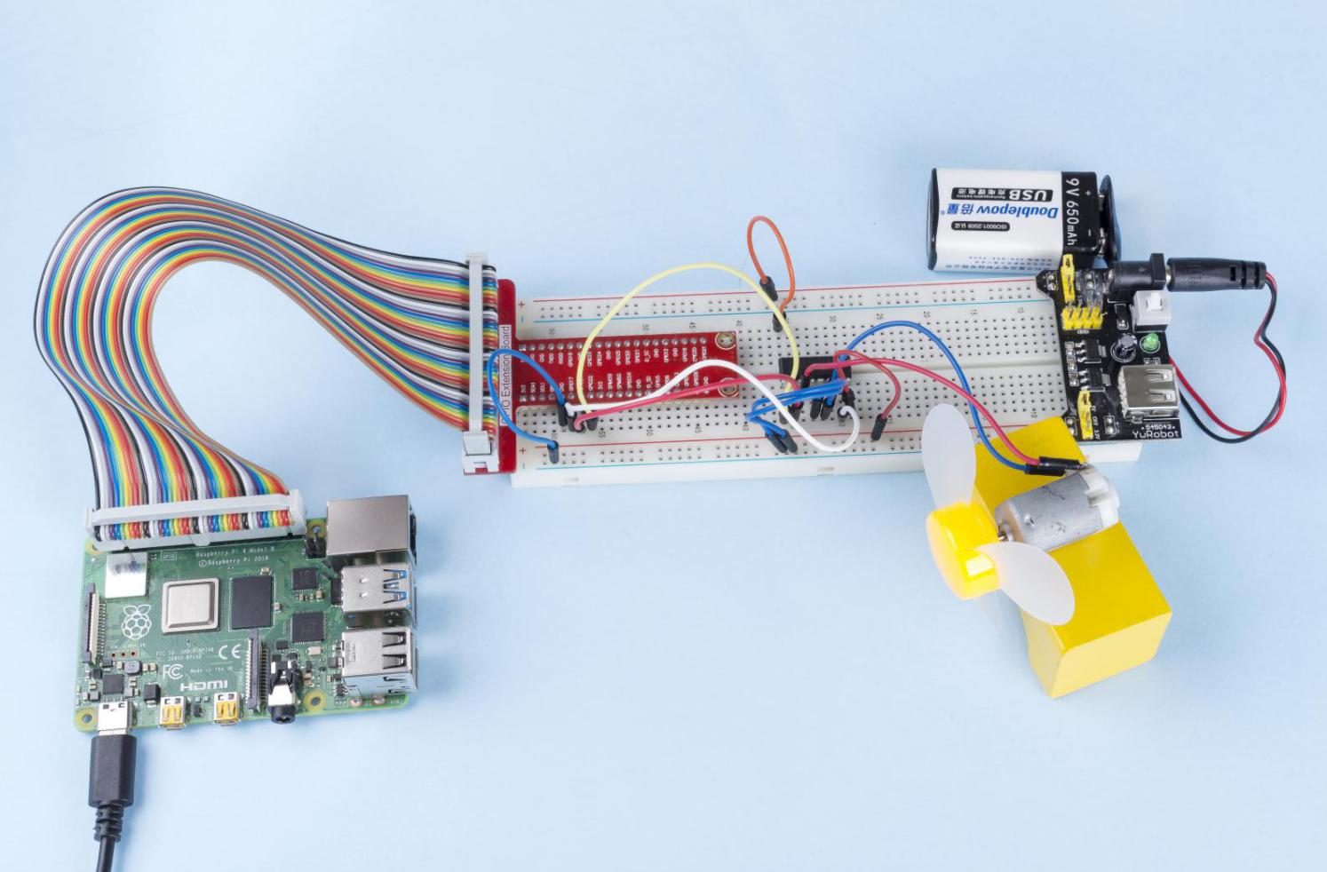
ステップ1: 回路を作る。

注釈
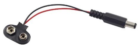
電源モジュールはキットの9Vバッテリーバックルで9Vバッテリーを適用できる。電源モジュールのジャンパキャップをブレッドボードの5Vバスストリップに挿入する。
C言語ユーザー向け
ステップ2: コードのフォルダーに入る。
cd ~/davinci-kit-for-raspberry-pi/c/1.3.1/
ステップ3: コンパイルする。
gcc 1.3.1_Motor.c -lwiringPi
ステップ4: EXEファイルを実行する。
sudo ./a.out
コードが実行されると、モーターは最初に5秒間時計回りに回転し、それから5秒間停止し、その後5秒間反時計回りに回転してから5秒間停止する。この一連の動作は繰り返し実行される。
コード
#include <wiringPi.h>
#include <stdio.h>

#define MotorPin1       0
#define MotorPin2       2
#define MotorEnable     3

int main(void){
    int i;
    if(wiringPiSetup() == -1){ //when initialize wiring failed, print messageto screen
        printf("setup wiringPi failed !");
        return 1;
    }

    pinMode(MotorPin1, OUTPUT);
    pinMode(MotorPin2, OUTPUT);
    pinMode(MotorEnable, OUTPUT);
    while(1){
        printf("Clockwise\n");
        delay(100);
        digitalWrite(MotorEnable, HIGH);
        digitalWrite(MotorPin1, HIGH);
        digitalWrite(MotorPin2, LOW);
        for(i=0;i<3;i++){
            delay(1000);
        }

        printf("Stop\n");
        delay(100);
        digitalWrite(MotorEnable, LOW);
        for(i=0;i<3;i++){
            delay(1000);
        }

        printf("Anti-clockwise\n");
        delay(100);
        digitalWrite(MotorEnable, HIGH);
        digitalWrite(MotorPin1, LOW);
        digitalWrite(MotorPin2, HIGH);
        for(i=0;i<3;i++){
            delay(1000);
        }

        printf("Stop\n");
        delay(100);
        digitalWrite(MotorEnable, LOW);
        for(i=0;i<3;i++){
            delay(1000);
        }
    }
    return 0;
}
コードの説明
digitalWrite(MotorEnable, HIGH);
L239Dを有効にする。
digitalWrite(MotorPin1, HIGH);
digitalWrite(MotorPin2, LOW);
2A(ピン7)に高レベルを設定する。1,2EN(ピン1)は高レベルなので、2Yは高レベルを出力する。
1Aに低レベルを設定すると、1Yが低レベルを出力し、モーターが回転する。
for(i=0;i<3;i++){
delay(1000);
}
このループは3 * 1000ms遅延する。
digitalWrite(MotorEnable, LOW)
1,2EN(ピン1)が低レベルの場合、L293Dは機能しない。モーターが回転を停止する。
digitalWrite(MotorPin1, LOW)
digitalWrite(MotorPin2, HIGH)
モーターの電流を逆にすると、モーターが逆回転する。
Python言語ユーザー向け
ステップ2: コードのフォルダーに入る。
cd ~/davinci-kit-for-raspberry-pi/python
ステップ3: 実行する。
sudo python3 1.3.1_Motor.py
コードが実行されると、モーターは最初に5秒間時計回りに回転し、それから5秒間停止し、その後5秒間反時計回りに回転してから5秒間停止する。この一連の動作は繰り返し実行される。
コード
注釈
以下のコードを 変更/リセット/コピー/実行/停止 できます。 ただし、その前に、 davinci-kit-for-raspberry-pi/python のようなソースコードパスに移動する必要があります。
import RPi.GPIO as GPIO
import time

dhtPin = 17

GPIO.setmode(GPIO.BCM)

MAX_UNCHANGE_COUNT = 100

STATE_INIT_PULL_DOWN = 1
STATE_INIT_PULL_UP = 2
STATE_DATA_FIRST_PULL_DOWN = 3
STATE_DATA_PULL_UP = 4
STATE_DATA_PULL_DOWN = 5

def readDht11():
    GPIO.setup(dhtPin, GPIO.OUT)
    GPIO.output(dhtPin, GPIO.HIGH)
    time.sleep(0.05)
    GPIO.output(dhtPin, GPIO.LOW)
    time.sleep(0.02)
    GPIO.setup(dhtPin, GPIO.IN, GPIO.PUD_UP)

    unchanged_count = 0
    last = -1
    data = []
    while True:
        current = GPIO.input(dhtPin)
        data.append(current)
        if last != current:
            unchanged_count = 0
            last = current
        else:
            unchanged_count += 1
            if unchanged_count > MAX_UNCHANGE_COUNT:
                break

    state = STATE_INIT_PULL_DOWN

    lengths = []
    current_length = 0

    for current in data:
        current_length += 1

        if state == STATE_INIT_PULL_DOWN:
            if current == GPIO.LOW:
                state = STATE_INIT_PULL_UP
            else:
                continue
        if state == STATE_INIT_PULL_UP:
            if current == GPIO.HIGH:
                state = STATE_DATA_FIRST_PULL_DOWN
            else:
                continue
        if state == STATE_DATA_FIRST_PULL_DOWN:
            if current == GPIO.LOW:
                state = STATE_DATA_PULL_UP
            else:
                continue
        if state == STATE_DATA_PULL_UP:
            if current == GPIO.HIGH:
                current_length = 0
                state = STATE_DATA_PULL_DOWN
            else:
                continue
        if state == STATE_DATA_PULL_DOWN:
            if current == GPIO.LOW:
                lengths.append(current_length)
                state = STATE_DATA_PULL_UP
            else:
                continue
    if len(lengths) != 40:
        #print ("Data not good, skip")
        return False

    shortest_pull_up = min(lengths)
    longest_pull_up = max(lengths)
    halfway = (longest_pull_up + shortest_pull_up) / 2
    bits = []
    the_bytes = []
    byte = 0

    for length in lengths:
        bit = 0
        if length > halfway:
            bit = 1
        bits.append(bit)
    #print ("bits: %s, length: %d" % (bits, len(bits)))
    for i in range(0, len(bits)):
        byte = byte << 1
        if (bits[i]):
            byte = byte | 1
        else:
            byte = byte | 0
        if ((i + 1) % 8 == 0):
            the_bytes.append(byte)
            byte = 0
    #print (the_bytes)
    checksum = (the_bytes[0] + the_bytes[1] + the_bytes[2] + the_bytes[3]) & 0xFF
    if the_bytes[4] != checksum:
        #print ("Data not good, skip")
        return False

    return the_bytes[0], the_bytes[2]

def main():

    while True:
        result = readDht11()
        if result:
            humidity, temperature = result
            print ("humidity: %s %%,  Temperature: %s C`" % (humidity, temperature))
        time.sleep(1)

def destroy():
    GPIO.cleanup()

if __name__ == '__main__':
    try:
        main()
    except KeyboardInterrupt:
        destroy()
コードの説明
def motor(direction):
    # Clockwise
    if direction == 1:
        # Set direction
        GPIO.output(MotorPin1, GPIO.HIGH)
        GPIO.output(MotorPin2, GPIO.LOW)
        # Enable the motor
        GPIO.output(MotorEnable, GPIO.HIGH)
        print ("Clockwise")
...
変数が direction である関数 motor() を作成する。
direction = 1 の条件が満たされると、モーターは時計回りに回転する。
direction = -1 の場合、モーターは反時計回りに回転する。
そして、 direction = 0 の条件下では、回転を停止する。
def main():
    # Define a dictionary to make the script more readable
    # CW as clockwise, CCW as counterclockwise, STOP as stop
    directions = {'CW': 1, 'CCW': -1, 'STOP': 0}
    while True:
        # Clockwise
        motor(directions['CW'])
        time.sleep(5)
        # Stop
        motor(directions['STOP'])
        time.sleep(5)
        # Anticlockwise
        motor(directions['CCW'])
        time.sleep(5)
        # Stop
        motor(directions['STOP'])
        time.sleep(5)
main() 関数で、CWが1、CCWの値が-1、0がStopを指す配列 directions[] を作成する。
コードが実行されると、モーターは最初に5秒間時計回りに回転し、それから5秒間停止し、その後5秒間反時計回りに回転してから5秒間停止する。この一連の動作は繰り返し実行される。
これで、モーターブレードが回転していることが分かる。
現象画像