Note
Hello, welcome to the SunFounder Raspberry Pi & Arduino & ESP32 Enthusiasts Community on Facebook! Dive deeper into Raspberry Pi, Arduino, and ESP32 with fellow enthusiasts.
Why Join?
Expert Support: Solve post-sale issues and technical challenges with help from our community and team.
Learn & Share: Exchange tips and tutorials to enhance your skills.
Exclusive Previews: Get early access to new product announcements and sneak peeks.
Special Discounts: Enjoy exclusive discounts on our newest products.
Festive Promotions and Giveaways: Take part in giveaways and holiday promotions.
👉 Ready to explore and create with us? Click [here] and join today!
1.3.1 Motor
Introduction
In this lesson, we will learn to how to use L293D to drive a DC motor and make it rotate clockwise and counterclockwise. Since the DC Motor needs a larger current, for safety purpose, here we use the Power Supply Module to supply motors.
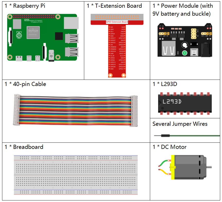
Components
Principle
L293D
L293D is a 4-channel motor driver integrated by chip with high voltage and high current. It’s designed to connect to standard DTL, TTL logic level, and drive inductive loads (such as relay coils, DC, Stepper Motors) and power switching transistors etc. DC Motors are devices that turn DC electrical energy into mechanical energy. They are widely used in electrical drive for their superior speed regulation performance.
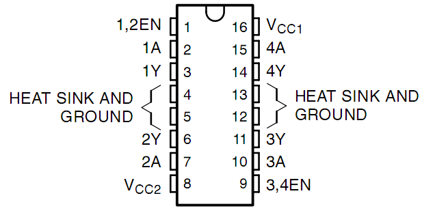
See the figure of pins below. L293D has two pins (Vcc1 and Vcc2) for power supply. Vcc2 is used to supply power for the motor, while Vcc1 to supply for the chip. Since a small-sized DC motor is used here, connect both pins to +5V.
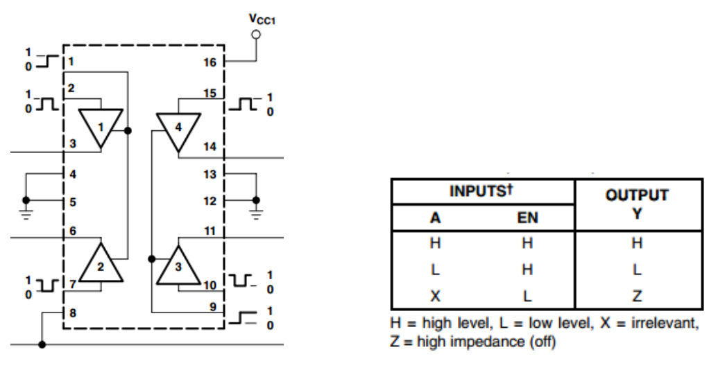
The following is the internal structure of L293D. Pin EN is an enable pin and only works with high level; A stands for input and Y for output. You can see the relationship among them at the right bottom. When pin EN is High level, if A is High, Y outputs high level; if A is Low, Y outputs Low level. When pin EN is Low level, the L293D does not work.
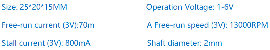
DC Motor
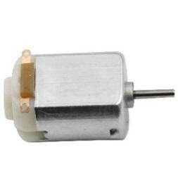
This is a 5V DC motor. It will rotate when you give the two terminals of the copper sheet one high and one low level. For convenience, you can weld the pins to it.
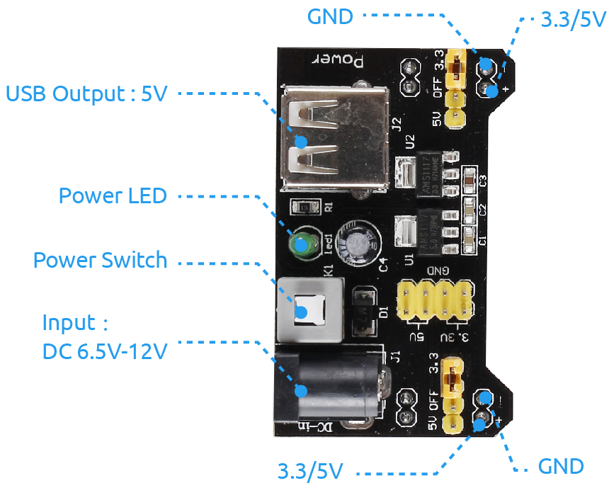
Power Supply Module
In this experiment, it needs large currents to drive the motor especially when it starts and stops, which will severely interfere with the normal work of Raspberry Pi. Therefore, we separately supply power for the motor by this module to make it run safely and steadily.
You can just plug it in the breadboard to supply power. It provides a voltage of 3.3V and 5V, and you can connect either via a jumper cap included.
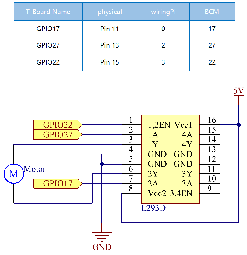
Schematic Diagram
Plug the power supply module in breadboard, and insert the jumper cap to pin of 5V, then it will output voltage of 5V. Connect pin 1 of L293D to GPIO22, and set it as high level. Connect pin2 to GPIO27, and pin7 to GPIO17, then set one pin high, while the other low. Thus you can change the motor’s rotation direction.
Experimental Procedures
Step 1: Build the circuit.
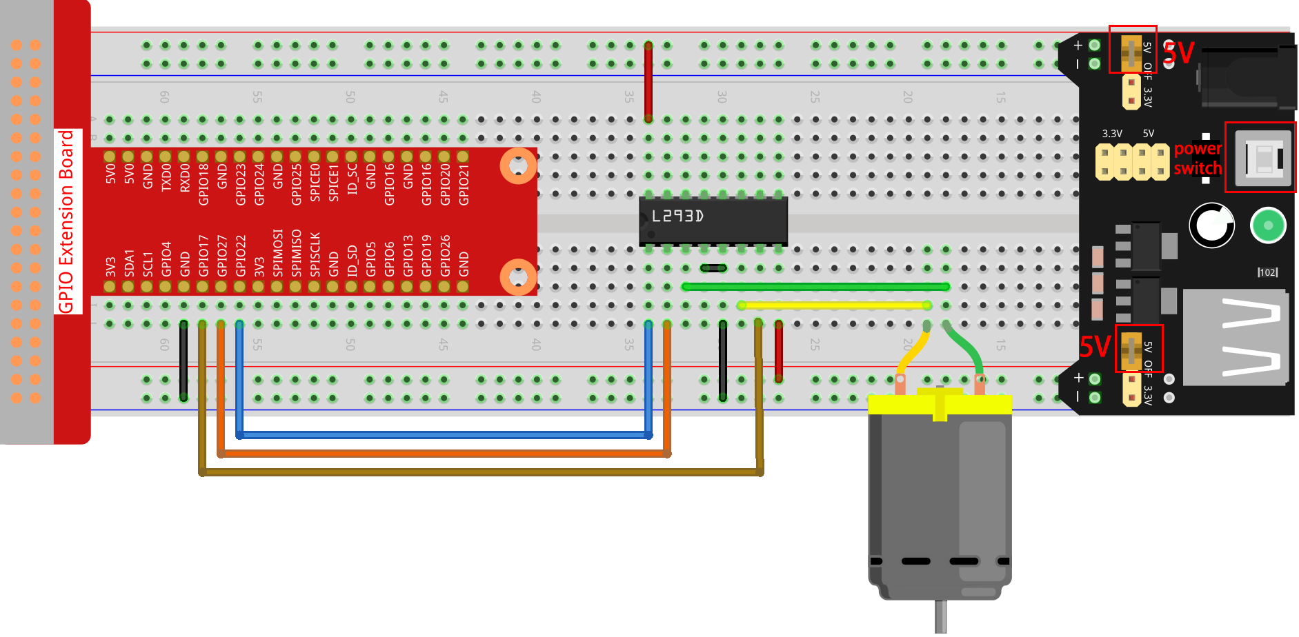
Note
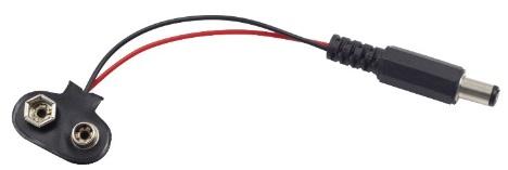
The power module can apply a 9V battery with the 9V Battery Buckle in the kit. Insert the jumper cap of the power module into the 5V bus strips of the breadboard.
Step 2: Get into the folder of the code.
cd ~/davinci-kit-for-raspberry-pi/c/1.3.1/
Step 3: Compile.
gcc 1.3.1_Motor.c -lwiringPi
Step 4: Run the executable file above.
sudo ./a.out
As the code runs, the motor first rotates clockwise for 5s then stops for 5s, after that, it rotates anticlockwise for 5s; subsequently, the motor stops for 5s. This series of actions will be executed repeatedly.
Note
If it does not work after running, or there is an error prompt: "wiringPi.h: No such file or directory", please refer to Install and Check the WiringPi.
Code
#include <wiringPi.h>
#include <stdio.h>

#define MotorPin1       0
#define MotorPin2       2
#define MotorEnable     3

int main(void){
    int i;
    if(wiringPiSetup() == -1){ //when initialize wiring failed, print messageto screen
        printf("setup wiringPi failed !");
        return 1;
    }

    pinMode(MotorPin1, OUTPUT);
    pinMode(MotorPin2, OUTPUT);
    pinMode(MotorEnable, OUTPUT);
    while(1){
        printf("Clockwise\n");
        delay(100);
        digitalWrite(MotorEnable, HIGH);
        digitalWrite(MotorPin1, HIGH);
        digitalWrite(MotorPin2, LOW);
        for(i=0;i<3;i++){
            delay(1000);
        }

        printf("Stop\n");
        delay(100);
        digitalWrite(MotorEnable, LOW);
        for(i=0;i<3;i++){
            delay(1000);
        }

        printf("Anti-clockwise\n");
        delay(100);
        digitalWrite(MotorEnable, HIGH);
        digitalWrite(MotorPin1, LOW);
        digitalWrite(MotorPin2, HIGH);
        for(i=0;i<3;i++){
            delay(1000);
        }

        printf("Stop\n");
        delay(100);
        digitalWrite(MotorEnable, LOW);
        for(i=0;i<3;i++){
            delay(1000);
        }
    }
    return 0;
}
Code Explanation
digitalWrite(MotorEnable, HIGH);
Enable the L239D.
digitalWrite(MotorPin1, HIGH);
digitalWrite(MotorPin2, LOW);
Set a high level for 2A(pin 7); since 1,2EN(pin 1) is in high level, 2Y will output high level.
Set a low level for 1A, then 1Y will output low level, and the motor will rotate.
for(i=0;i<3;i++){
delay(1000);
}
this loop is to delay for 3*1000ms.
digitalWrite(MotorEnable, LOW)
If 1,2EN (pin1) is in low level, L293D does not work. Motor stops rotating.
digitalWrite(MotorPin1, LOW)
digitalWrite(MotorPin2, HIGH)
Reverse the current flow of the motor, then the motor will rotate reversely.