5.13 Interrupt
If you use some delay() in a project that uses sensors, you may find that when you trigger these sensors, the program may have no effect.
This is because the delay statement will cause the program to suspend, and the program will not be able to obtain the signal sent by the sensor to the main control board.
In this case, interrupt can be used. Interrupt allows the program not to miss a pulse.
In this chapter, we use the active buzzer and buttons to experience the process of using interrupt.
In the loop() function, delay(1000) is used to count seconds.
Put the button to control the buzzer into the ISR, so that it will not be disturbed by the delay and complete the task smoothly.
Note
ISRs are special kinds of functions that have some unique limitations most other functions do not have. An ISR cannot have any parameters, and they shouldn’t return anything. Generally, an ISR should be as short and fast as possible. If your sketch uses multiple ISRs, only one can run at a time, other interrupts will be executed after the current one finishes in an order that depends on the priority they have.
Required Components
In this project, we need the following components.
It’s definitely convenient to buy a whole kit, here’s the link:
Name |
ITEMS IN THIS KIT |
LINK |
|---|---|---|
3 in 1 Starter Kit |
380+ |
You can also buy them separately from the links below.
COMPONENT INTRODUCTION |
PURCHASE LINK |
|---|---|
- |
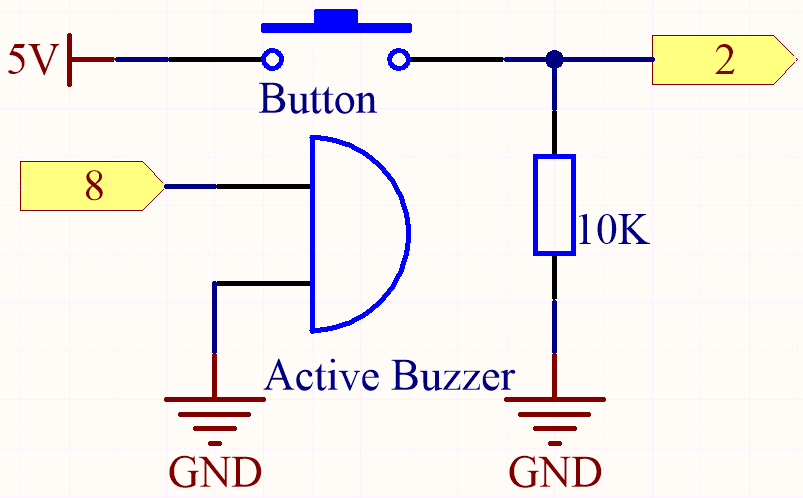
Schematic
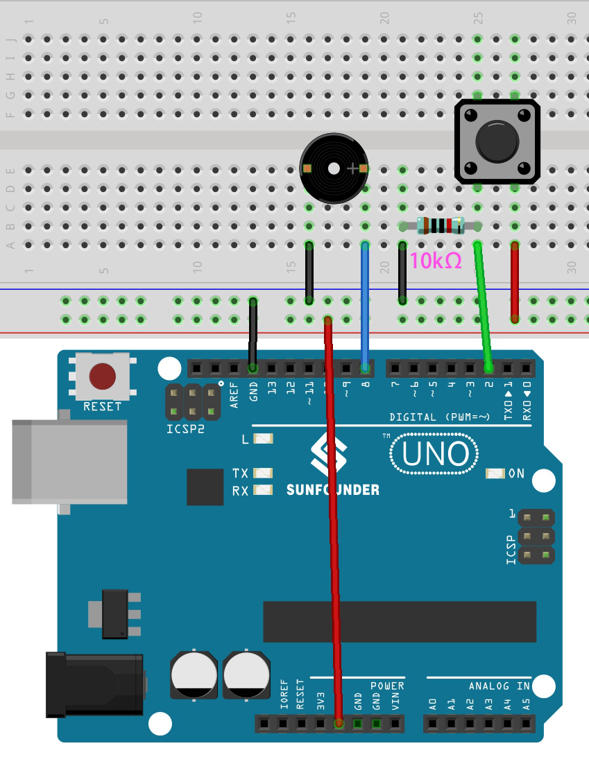
Wiring
Code
Note
Open the
5.13.interrupt.inofile under the path of3in1-kit\basic_project\5.13.interrupt.Or copy this code into Arduino IDE.
Or upload the code through the Arduino Web Editor.
After the code is successfully uploaded, turn on the Serial Monitor and you will see an auto-incrementing number printed out every second. If you press the button, the buzzer will sound. The button-controlled buzzer function and the timing function do not conflict with each other.
How it works?
attachInterrupt(digitalPinToInterrupt(pin), ISR, mode): Add an interrupt.- Syntax
attachInterrupt(digitalPinToInterrupt(pin), ISR, mode)
- Parameters
pin: the Arduino pin number. You should usedigitalPinToInterrupt(pin)to convert the actual digital pin to a specific interrupt number. For example, if you connect to pin 3, use itsdigitalPinToInterrupt(3)as the first parameter.ISR: the ISR to call when the interrupt occurs; this function must take no parameters and return nothing. This function is sometimes referred to as an interrupt service routine.mode: defines when the interrupt should be triggered. Four constants are predefined as valid values:LOWto trigger the interrupt whenever the pin is low,CHANGEto trigger the interrupt whenever the pin changes value.RISINGto trigger when the pin goes from low to high.FALLINGfor when the pin goes from high to low.
Note
Different main control boards can use interrupt pins differently. On R3 board, only pin 2 and pin 3 can use interrupt.