5.14 Calibration
When you use analog input components, such as photoresistors, soil moisture sensors, etc., you may find that their reading range is not 0 to 1023, but rather a range like 0 to 800 or 600 to 1000, because it is impossible to reach the limits of these devices with normal use.
In this case, a technique for calibrating the sensor inputs can be used. During startup, have the control board measure the sensor readings for five seconds and record the highest and lowest readings. This five-second reading defines the minimum and maximum expected values of the readings taken during the cycle.
In this project, we use a photoresistor and a passive buzzer to implement a theremin -like game using the calibration technique described above.
Note
The theremin is an electronic musical instrument that requires no physical contact. It generates different tones by sensing the position of the player’s hands.
Required Components
In this project, we need the following components.
It’s definitely convenient to buy a whole kit, here’s the link:
Name |
ITEMS IN THIS KIT |
LINK |
|---|---|---|
3 in 1 Starter Kit |
380+ |
You can also buy them separately from the links below.
COMPONENT INTRODUCTION |
PURCHASE LINK |
|---|---|
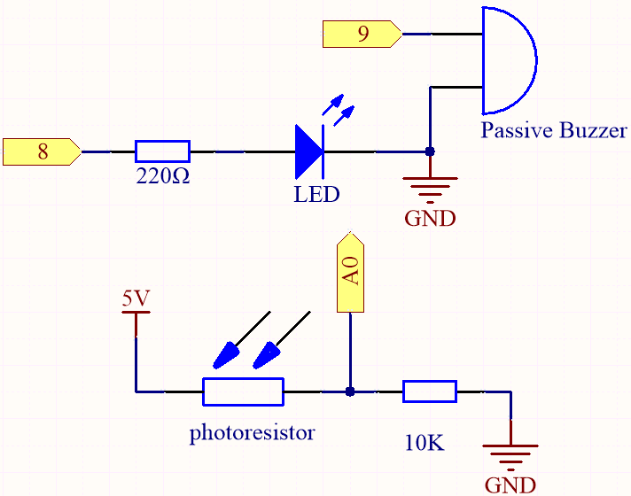
Schematic
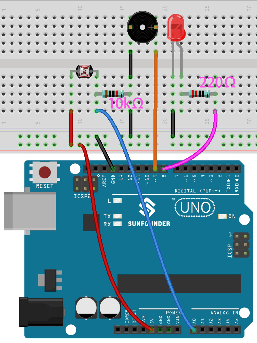
Wiring
Code
Note
Open the
5.14.calibration.inofile under the path of3in1-kit\basic_project\5.14.calibration.Or copy this code into Arduino IDE.
Or upload the code through the Arduino Web Editor.
After the code is uploaded successfully, the LED will light up, and we will have 5 seconds to calibrate the detection range of the photoresistor. This is because we may be in a different light environment each time we use it (e.g. the light intensity is different between midday and dusk).
At this time, we need to swing our hands up and down on top of the photoresistor, and the movement range of the hand will be calibrated to the playing range of this instrument.
After 5 seconds, the LED will go out and we can wave our hands on the photoresistor to play.
How it works?
Set the initial values and pins of all components.
const int buzzerPin = 9;
const int ledPin = 8;
const int photocellPin = A0;  //photoresistor attach to A2

int lightLow = 1023;
int lightHigh = 0;

int sensorValue = 0;        // value read from the sensor
int pitch = 0;           // sensor value converted into LED 'bars'

unsigned long previousMillis = 0;
const long interval = 5000;
Set up a calibration process in
setup().void setup() { pinMode(buzzerPin, OUTPUT);// make all the LED pins outputs pinMode(ledPin, OUTPUT); // make the LED pin output /* calibrate the photoresistor max & min values */ previousMillis = millis(); digitalWrite(ledPin, HIGH); while (millis() - previousMillis <= interval) { sensorValue = analogRead(photocellPin); if (sensorValue > lightHigh) { lightHigh = sensorValue; } if (sensorValue < lightLow) { lightLow = sensorValue; } } digitalWrite(ledPin, LOW); }
The work flow is as follows.
using
millis()for timing with an interval of 5000ms.
previousMillis = millis();
...
while (millis() - previousMillis <= interval) {
...
}
During these five seconds, wave a hand around the photoresistor, the maximum and minimum values of the detected light are recorded and assigned to
lightHighandlightLowrespectively.
sensorValue = analogRead(photocellPin);
if (sensorValue > lightHigh) {
    lightHigh = sensorValue;
}
if (sensorValue < lightLow) {
    lightLow = sensorValue;
}
Now you can start playing this Thermin. Read the value of the photoresistor to
sensorValueand map it from the small range to the large range to be used as the frequency of the buzzer.void loop() { /* play*/ sensorValue = analogRead(photocellPin); //read the value of A0 pitch = map(sensorValue, lightLow, lightHigh, 50, 6000); // map to the buzzer frequency if (pitch > 50) { tone(buzzerPin, pitch, 20); } delay(10); }