注釈
こんにちは、SunFounderのRaspberry Pi & Arduino & ESP32愛好家コミュニティへようこそ!Facebook上でRaspberry Pi、Arduino、ESP32についてもっと深く掘り下げ、他の愛好家と交流しましょう。
参加する理由は?
エキスパートサポート:コミュニティやチームの助けを借りて、販売後の問題や技術的な課題を解決します。
学び&共有:ヒントやチュートリアルを交換してスキルを向上させましょう。
独占的なプレビュー:新製品の発表や先行プレビューに早期アクセスしましょう。
特別割引:最新製品の独占割引をお楽しみください。
祭りのプロモーションとギフト:ギフトや祝日のプロモーションに参加しましょう。
👉 私たちと一緒に探索し、創造する準備はできていますか?[ここ]をクリックして今すぐ参加しましょう!
1.1.6 LEDドットマトリックスモジュール
はじめに
このプロジェクトでは、LEDマトリックスモジュールについて学びます。LEDマトリックスモジュールは、MAX7219ドライバを使用して8x8のLEDマトリックスを駆動します。
必要な部品
このプロジェクトでは、以下のコンポーネントが必要です。

一式を購入するのが便利です。リンクは以下のとおりです。
名前 |
このキットのアイテム |
リンク |
|---|---|---|
Raphael Kit |
337 |
以下のリンクから個別に購入することもできます。
コンポーネントの紹介 |
購入リンク |
|---|---|
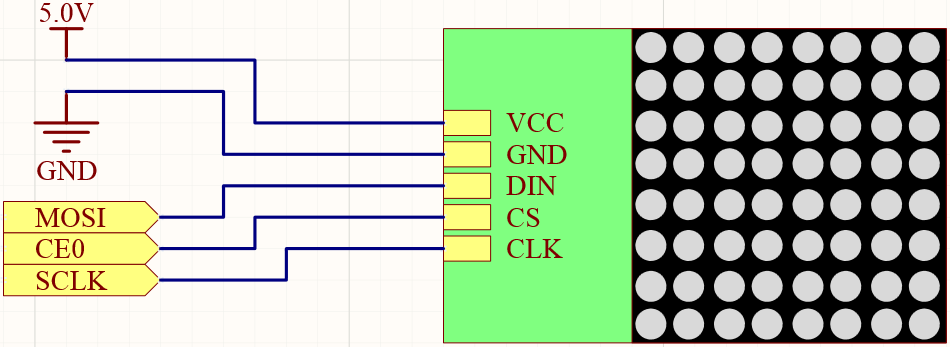
回路図
T-Board Name |
physical |
wiringPi |
BCM |
SPIMOSI |
Pin 19 |
12 |
MOSI |
SPICE0 |
pin 24 |
10 |
CE0 |
SPISCLK |
Pin 23 |
14 |
SCLK |
実験の手順
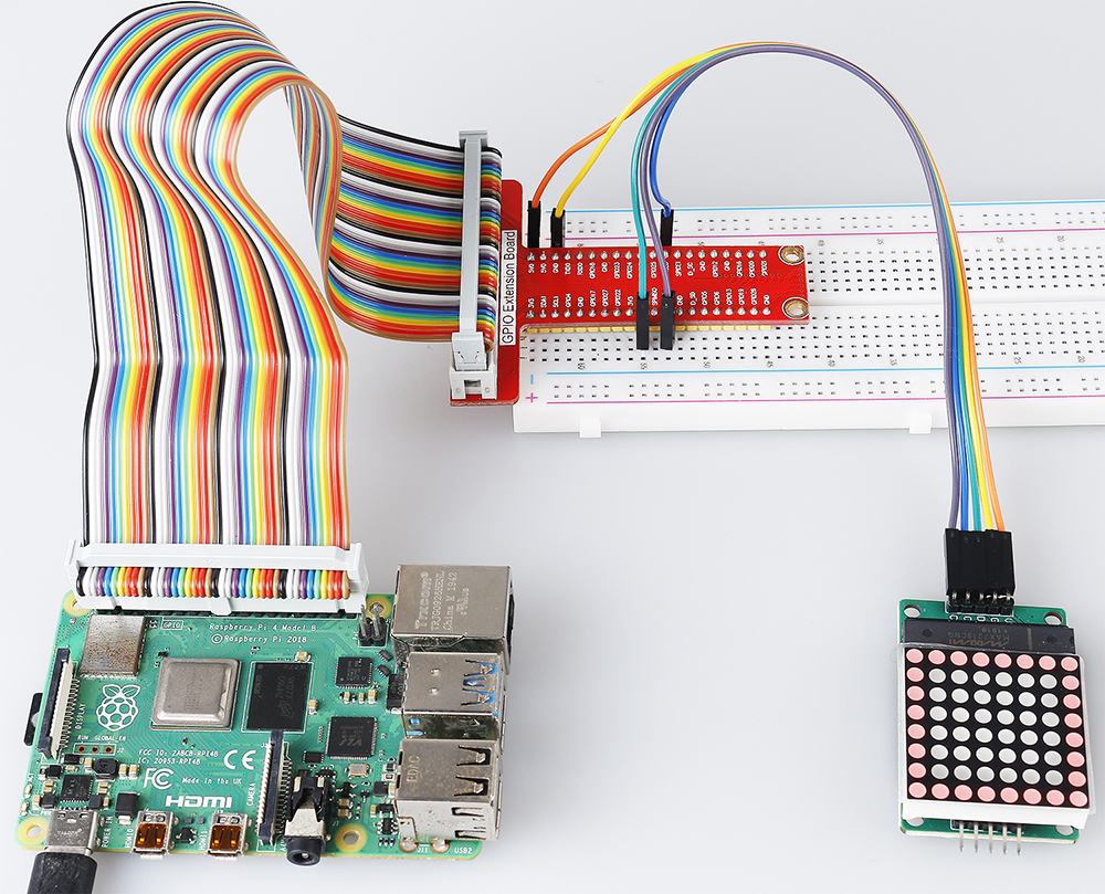
ステップ1: 回路を組む。

ステップ2: 実験を開始する前にSPIをオンにしてください。詳細は SPI 設定 を参照してください。
ステップ3: コードのフォルダに移動する。
cd ~/raphael-kit/c/1.1.6/
ステップ4: コードをコンパイルする。
make
ステップ5: 実行可能ファイルを実行する。
sudo ./1.1.6_LedMatrix
コードを実行すると、LED ドットマトリックスはスクエア、ハート、数字 0 から 9 まで順に表示されます。
注釈
実行後に動作しない、またはエラープロンプトが表示される場合:「wiringPi.h: No such file or directory」、 WiringPiのインストールと確認 を参照してください。
コード
#include <wiringPi.h>
#include <wiringPiSPI.h>
#include <stdio.h>

#define SPI_CHANNEL    0           // Define SPI channel (0 or 1)
#define SPI_SPEED      1000000     // SPI speed set to 1 MHz

// Function to write data to a MAX7219 register
void max7219_write(unsigned char address, unsigned char data) {
    unsigned char buffer[2];
    buffer[0] = address;   // Register address to write to
    buffer[1] = data;      // Data to write into the register
    wiringPiSPIDataRW(SPI_CHANNEL, buffer, 2);  // Send data via SPI
}

// Function to initialize the MAX7219 display module
void max7219_init() {
    max7219_write(0x09, 0x00); // Decode Mode: No decoding for digits (useful for 7-segment displays)
    max7219_write(0x0A, 0x03); // Intensity: Set brightness level (0x00 to 0x0F)
    max7219_write(0x0B, 0x07); // Scan Limit: Display digits 0-7 (all 8 digits)
    max7219_write(0x0C, 0x01); // Shutdown Register: Normal operation (not in shutdown mode)
    max7219_write(0x0F, 0x00); // Display Test: Normal operation (no test mode)

    // Clear all digits on the display
    for (int i = 1; i <= 8; i++) {
        max7219_write(i, 0x00); // Write 0 to each digit register
    }
}

// Function to display a pattern on the MAX7219
void max7219_display(unsigned char *data) {
    for (int i = 1; i <= 8; i++) {
        max7219_write(i, data[i - 1]); // Write each row of the pattern to the display
    }
}

// Function to display a pattern for a specified duration
void display_pattern(const unsigned char pattern[8], int delay_ms) {
    max7219_display((unsigned char *)pattern); // Display the pattern
    delay(delay_ms);                           // Wait for the specified time in milliseconds
}

// Array of patterns to display
const unsigned char patterns[][8] = {
    // Square pattern
    {
        0b11111111, // Row 1
        0b10000001, // Row 2
        0b10000001, // Row 3
        0b10000001, // Row 4
        0b10000001, // Row 5
        0b10000001, // Row 6
        0b10000001, // Row 7
        0b11111111  // Row 8
    },
    // Heart pattern
    {
        0b01100110, // Row 1
        0b11111111, // Row 2
        0b11111111, // Row 3
        0b11111111, // Row 4
        0b01111110, // Row 5
        0b00111100, // Row 6
        0b00011000, // Row 7
        0b00000000  // Row 8
    },
    // Number 0
    {
        0b00111100, // Row 1
        0b01100110, // Row 2
        0b11000011, // Row 3
        0b11000011, // Row 4
        0b11000011, // Row 5
        0b11000011, // Row 6
        0b01100110, // Row 7
        0b00111100  // Row 8
    },
    // Number 1
    {
        0b00011000, // Row 1
        0b00111000, // Row 2
        0b01111000, // Row 3
        0b00011000, // Row 4
        0b00011000, // Row 5
        0b00011000, // Row 6
        0b01111110, // Row 7
        0b01111110  // Row 8
    },
    // Number 2
    {
        0b01111110, // Row 1
        0b11000011, // Row 2
        0b00000011, // Row 3
        0b00001110, // Row 4
        0b00110000, // Row 5
        0b11000000, // Row 6
        0b11111111, // Row 7
        0b00000000  // Row 8
    },
    // Number 3
    {
        0b01111110, // Row 1
        0b11000011, // Row 2
        0b00000011, // Row 3
        0b00111110, // Row 4
        0b00000011, // Row 5
        0b11000011, // Row 6
        0b01111110, // Row 7
        0b00000000  // Row 8
    },
    // Number 4
    {
        0b00001110, // Row 1
        0b00011110, // Row 2
        0b00110110, // Row 3
        0b01100110, // Row 4
        0b11111111, // Row 5
        0b00000110, // Row 6
        0b00000110, // Row 7
        0b00000000  // Row 8
    },
    // Number 5
    {
        0b11111111, // Row 1
        0b11000000, // Row 2
        0b11111110, // Row 3
        0b00000011, // Row 4
        0b00000011, // Row 5
        0b11000011, // Row 6
        0b01111110, // Row 7
        0b00000000  // Row 8
    },
    // Number 6
    {
        0b00111110, // Row 1
        0b01100000, // Row 2
        0b11000000, // Row 3
        0b11111110, // Row 4
        0b11000011, // Row 5
        0b11000011, // Row 6
        0b01111110, // Row 7
        0b00000000  // Row 8
    },
    // Number 7
    {
        0b11111111, // Row 1
        0b11000011, // Row 2
        0b00000110, // Row 3
        0b00001100, // Row 4
        0b00011000, // Row 5
        0b00110000, // Row 6
        0b00110000, // Row 7
        0b00000000  // Row 8
    },
    // Number 8
    {
        0b01111110, // Row 1
        0b11000011, // Row 2
        0b11000011, // Row 3
        0b01111110, // Row 4
        0b11000011, // Row 5
        0b11000011, // Row 6
        0b01111110, // Row 7
        0b00000000  // Row 8
    },
    // Number 9
    {
        0b01111110, // Row 1
        0b11000011, // Row 2
        0b11000011, // Row 3
        0b01111111, // Row 4
        0b00000011, // Row 5
        0b00000110, // Row 6
        0b01111100, // Row 7
        0b00000000  // Row 8
    },
};

int main() {
    if (wiringPiSetup() == -1) {
        printf("Failed to initialize WiringPi\n");
        return 1;
    }

    if (wiringPiSPISetup(SPI_CHANNEL, SPI_SPEED) == -1) {
        printf("Failed to initialize SPI\n");
        return 1;
    }

    max7219_init();  // Initialize the MAX7219 module

    // Display patterns in a loop
    while (1) {
        // Display the square pattern
        display_pattern(patterns[0], 1000);  // Display for 1000 milliseconds

        // Display the heart pattern
        display_pattern(patterns[1], 1000);

        // Display numbers 0-9
        for (int i = 2; i <= 11; i++) {
            display_pattern(patterns[i], 1000);
        }
    }

    return 0;
}
コード説明
必要なヘッダファイルをインクルード:
wiringPi.h: WiringPi ライブラリを使用して GPIO を制御するための関数を提供します。wiringPiSPI.h: SPI 通信を行うための関数を提供します。stdio.h: 標準の入出力関数(例:printfなど)を提供します。
定義:
SPI_CHANNEL: 使用する SPI チャンネル(0 または 1)を指定します。SPI_SPEED: SPI 通信速度を 1 MHz に設定します。
#define SPI_CHANNEL    0           // Define SPI channel (0 or 1)
#define SPI_SPEED      1000000     // SPI speed set to 1 MHz
関数
max7219_write:MAX7219ディスプレイドライバの特定のレジスタにデータを送信します。address: 書き込み先のレジスタのアドレス。data: レジスタに書き込むデータ。アドレスとデータを含むバッファを作成します。
wiringPiSPIDataRWを使用して、バッファを SPI 経由で送信します。
void max7219_write(unsigned char address, unsigned char data) {
    unsigned char buffer[2];
    buffer[0] = address;   // Register address to write to
    buffer[1] = data;      // Data to write into the register
    wiringPiSPIDataRW(SPI_CHANNEL, buffer, 2);  // Send data via SPI
}
関数
max7219_init:MAX7219ディスプレイモジュールを必要な設定で初期化します。デコードモードを「デコードなし」に設定(LED を直接制御するため)。
明るさ(輝度)を中程度のレベル(0x03)に設定。
スキャンリミットを 7 に設定し、ディスプレイのすべての 8 桁(行)を有効にします。
シャットダウンモードを終了してディスプレイをオンにします。
ディスプレイテストモードを無効化します。
すべての桁のレジスタに 0x00 を書き込むことでディスプレイをクリアします。
void max7219_init() {
    max7219_write(0x09, 0x00); // Decode Mode: No decoding for digits (useful for 7-segment displays)
    max7219_write(0x0A, 0x03); // Intensity: Set brightness level (0x00 to 0x0F)
    max7219_write(0x0B, 0x07); // Scan Limit: Display digits 0-7 (all 8 digits)
    max7219_write(0x0C, 0x01); // Shutdown Register: Normal operation (not in shutdown mode)
    max7219_write(0x0F, 0x00); // Display Test: Normal operation (no test mode)

    // Clear all digits on the display
    for (int i = 1; i <= 8; i++) {
        max7219_write(i, 0x00); // Write 0 to each digit register
    }
}
関数
max7219_display: 指定した 8 バイトのパターンでディスプレイを更新します。data: 表示するパターンを含む配列。各 8 行(桁)を繰り返して対応するデータを書き込みます。
void max7219_display(unsigned char *data) {
    for (int i = 1; i <= 8; i++) {
        max7219_write(i, data[i - 1]); // Write each row of the pattern to the display
    }
}
関数
display_pattern: 指定した時間表示するためのパターンを表示します。pattern: 表示するパターン(8 バイトの配列)。delay_ms: パターンを表示する時間の長さ(ミリ秒)。max7219_displayを呼び出してパターンを表示します。指定された時間だけ待機するために
delayを使用します。
void display_pattern(const unsigned char pattern[8], int delay_ms) {
    max7219_display((unsigned char *)pattern); // Display the pattern
    delay(delay_ms);                           // Wait for the specified time in milliseconds
}
配列パターン:
スクエア、ハート、および数字 0 - 9 の事前定義されたパターンを含む。
各パターンは、8x8 LED マトリックスの 8 行を表す 8 バイトの配列。
各バイトは、バイナリ表記を使用し、各ビットが LED を表します(1 はオン、0 はオフ)。
const unsigned char patterns[][8] = {
    // Square pattern
    {
        0b11111111, // Row 1
        0b10000001, // Row 2
        0b10000001, // Row 3
        0b10000001, // Row 4
        0b10000001, // Row 5
        0b10000001, // Row 6
        0b10000001, // Row 7
        0b11111111  // Row 8
    },
    ...
    // Number 9
    {
        ...
    },
};
メイン関数:
WiringPiおよびSPIインターフェースを初期化します。if (wiringPiSetup() == -1) { printf("Failed to initialize WiringPi\n"); return 1; } if (wiringPiSPISetup(SPI_CHANNEL, SPI_SPEED) == -1) { printf("Failed to initialize SPI\n"); return 1; }
max7219_initを呼び出してMAX7219モジュールを設定します。max7219_init(); // Initialize the MAX7219 module
無限ループに入り、パターンを継続的に表示します。各パターンを 1 秒間表示してから次に進みます。
while (1) {
    // Display the square pattern
    display_pattern(patterns[0], 1000);  // Display for 1000 milliseconds

    // Display the heart pattern
    display_pattern(patterns[1], 1000);

    // Display numbers 0-9
    for (int i = 2; i <= 11; i++) {
        display_pattern(patterns[i], 1000);
    }
}
パターンの理解
バイナリ表記:
各パターンは、バイナリリテラル(
0bプレフィックス)を使用して定義されています。各バイトは、8x8 LED マトリックス上の 1 行に対応します。
各バイト内の各ビットがその行内の列(LED)を表します。
最上位ビット(左端)は、左端の最初の LED に対応します。
カスタムパターンの作成:
8 バイトの新しい配列を定義して、新しいパターンを作成できます。
各パターンは
patterns配列に追加できます。メイン関数のディスプレイループを更新して、新しいパターンを含めます。
調整とカスタマイズ
明るさの変更:
max7219_initで輝度レベルを変更します:max7219_write(0x0A, brightness_level); // brightness_level between 0x00 and 0x0F
表示時間の変更:
display_pattern呼び出しでdelay_msパラメータを変更して、各パターンの表示時間を調整します。
現象の画像