Note
Hello, welcome to the SunFounder Raspberry Pi & Arduino & ESP32 Enthusiasts Community on Facebook! Dive deeper into Raspberry Pi, Arduino, and ESP32 with fellow enthusiasts.
Why Join?
Expert Support: Solve post-sale issues and technical challenges with help from our community and team.
Learn & Share: Exchange tips and tutorials to enhance your skills.
Exclusive Previews: Get early access to new product announcements and sneak peeks.
Special Discounts: Enjoy exclusive discounts on our newest products.
Festive Promotions and Giveaways: Take part in giveaways and holiday promotions.
👉 Ready to explore and create with us? Click [here] and join today!
Show Number
In this project, we use processing to drive a 7-segment display to show a figure from 0 to 9 and A to F.
Required Components
In this project, we need the following components.
It’s definitely convenient to buy a whole kit, here’s the link:
Name |
ITEMS IN THIS KIT |
LINK |
|---|---|---|
Raphael Kit |
337 |
You can also buy them separately from the links below.
COMPONENT INTRODUCTION |
PURCHASE LINK |
|---|---|
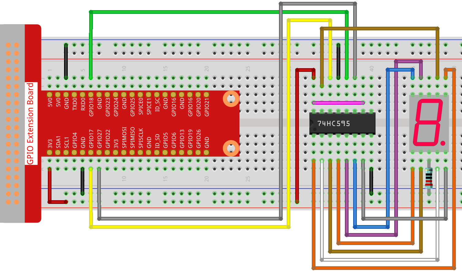
Wiring
Sketch
import processing.io.*;

int SDI=17;   //serial data input
int RCLK=18;  //memory clock input(STCP)
int SRCLK =27;   //shift register clock input(SHCP)


int[] SegCode= {0x3f,0x06,0x5b,0x4f,0x66,0x6d,0x7d,0x07,0x7f,0x6f,0x77,0x7c,0x39,0x5e,0x79,0x71};

void hc595_shift(int dat){
  int i;

  for(i=0;i<8;i++){
        int n=(0x80 & (dat << i));
        if ( n==0){
          GPIO.digitalWrite(SDI, 0);
        } else {
          GPIO.digitalWrite(SDI, 1);
        }
        GPIO.digitalWrite(SRCLK, 1);
        delay(1);
        GPIO.digitalWrite(SRCLK, 0);
  }

        GPIO.digitalWrite(RCLK, 1);
        delay(1);
        GPIO.digitalWrite(RCLK, 0);
}

void setup() {
        size(400, 200);
        frameRate(10);

        GPIO.pinMode(SDI, GPIO.OUTPUT);
        GPIO.pinMode(RCLK, GPIO.OUTPUT);
        GPIO.pinMode(SRCLK, GPIO.OUTPUT);

        GPIO.digitalWrite(SDI, 0);
        GPIO.digitalWrite(RCLK, 0);
        GPIO.digitalWrite(SRCLK, 0);

        fill(0,25,88);
        textAlign(CENTER,CENTER);
        textSize(height*0.8);
}

void draw() {

        background(255);
        int number = (frameCount%100)/10;
        text(number, width/2, height/2);
        hc595_shift(SegCode[number]);
}
How it works?
Import processing.io.* and use the GPIO function library to control the digital tube pins.
Define array SegCode = {0x3f,0x06,0x5b,0x4f,0x66,0x6d,0x7d,0x07,0x7f,0x6f,0x77,0x7c,0x39,0x5e,0x79,0x71}
which represents a segment code array from 0 to F in Hexadecimal (Common cathode).
setup() function sets the three pins SDI,RCLK and SRCLK as output, and the initial data as 0.
hc595_shift(int dat) function is used to shift the SegCode to 74HC595.
void hc595_shift(int dat){
  int i;

  for(i=0;i<8;i++){
        int n=(0x80 & (dat << i));
        if ( n==0){
          GPIO.digitalWrite(SDI, 0);
        } else {
          GPIO.digitalWrite(SDI, 1);
        }
        GPIO.digitalWrite(SRCLK, 1);
        delay(1);
        GPIO.digitalWrite(SRCLK, 0);
  }

        GPIO.digitalWrite(RCLK, 1);
        delay(1);
        GPIO.digitalWrite(RCLK, 0);
}
n=(0x80 & (dat << i)) means to shift dat to the left by i bits and then do the & operation with 0x80.
The rule of & operation is that when both sides of & are 1, the result is 1, otherwise the result is 0.
For example, we assume dat=0x3f,i=2(0011 1111 << 2 shift to 1111 1100), then 1111 1100 & 1000 0000 (0x80)) = 1000 0000.
At last assign the dat data to SDI(DS) by bits.
digitalWrite(SRCLK, 1) when SRCLK generates a rising edge pulse from 0 to 1, the data will be transferred from the DS register to the shift register;
digitalWrite(RCLK, 1) when RCLK generates a rising edge pulse from 0 to 1, the data will be transferred from the shift register to the storage register.
fill(0,25,88);
textAlign(CENTER,CENTER);
textSize(height*0.8);
The fill() function used in setup() can fill the text color, textAlign(CENTER,CENTER) is used to center the text, textSize(height*0.8) change the text height to 0.8 times the original.
These functions can customize the text style displayed on the processing
void draw() {

        background(255);
        int number = (frameCount%100)/10;
        text(number, width/2, height/2);
        hc595_shift(SegCode[number]);
}
The frameCount is a seed, which is related to frameRate.
By default frameRate is 60, which means that frameCount will accumulate 60 times per second.
Then we can let processing and 7-segment display to show the figure from 0 to 9 and A to F simultaneously.