Note
Hello, welcome to the SunFounder Raspberry Pi & Arduino & ESP32 Enthusiasts Community on Facebook! Dive deeper into Raspberry Pi, Arduino, and ESP32 with fellow enthusiasts.
Why Join?
Expert Support: Solve post-sale issues and technical challenges with help from our community and team.
Learn & Share: Exchange tips and tutorials to enhance your skills.
Exclusive Previews: Get early access to new product announcements and sneak peeks.
Special Discounts: Enjoy exclusive discounts on our newest products.
Festive Promotions and Giveaways: Take part in giveaways and holiday promotions.
👉 Ready to explore and create with us? Click [here] and join today!
Blinking Dot
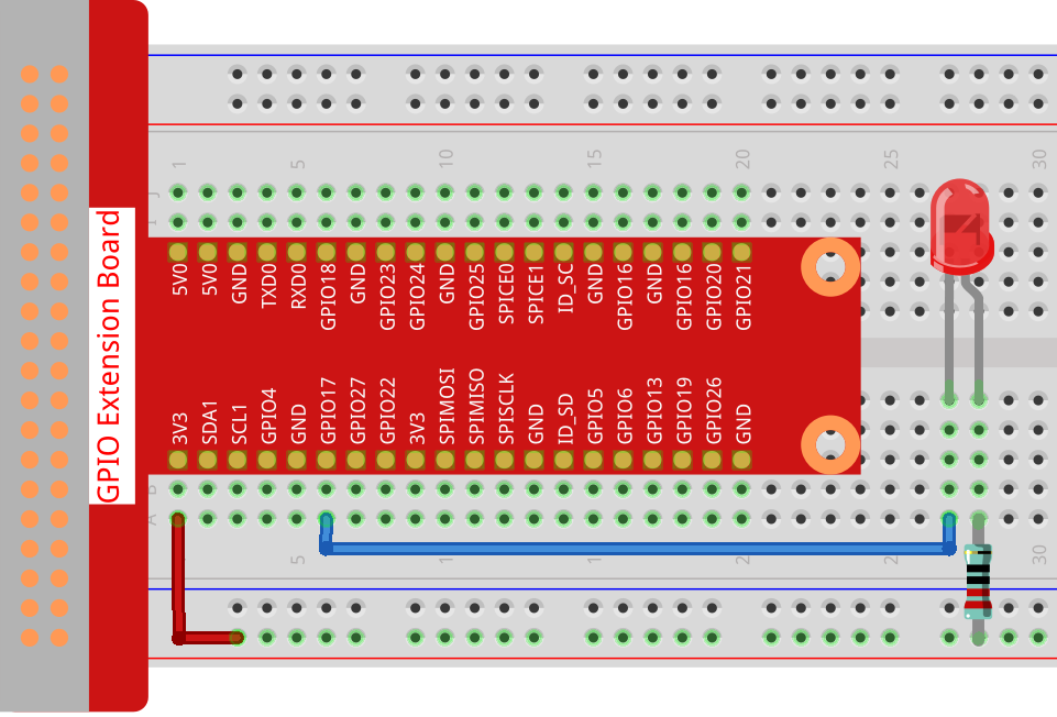
In this project, we will draw a dot on Processing, which blinks synchronously with the LED. Please build the circuit as shown in the diagram and run the sketch.
Required Components
In this project, we need the following components.
It’s definitely convenient to buy a whole kit, here’s the link:
Name |
ITEMS IN THIS KIT |
LINK |
|---|---|---|
Raphael Kit |
337 |
You can also buy them separately from the links below.
COMPONENT INTRODUCTION |
PURCHASE LINK |
|---|---|
Wiring
Sketch
import processing.io.*;
int ledPin = 17;
boolean state = true;

void setup() {
    size(100, 100);
    frameRate(2); //set frame rate
    GPIO.pinMode(ledPin, GPIO.OUTPUT); //set the ledPin to output mode
}

void draw() {
    state = !state;
    if (state==true) {
        GPIO.digitalWrite(ledPin, GPIO.LOW); //led on
        fill(255, 0, 0); //set the fill color of led on
    } else {
        GPIO.digitalWrite(ledPin, GPIO.HIGH); //led off
        fill(155); //set the fill color of led off
    }
    ellipse(width/2, height/2, width*0.75, height*0.75);
}
How it works?
At the beginning of the sketch, you need to embed Processing’s GPIO function library by import processing.io.*;, which is indispensable for circuit experiments.
Frame rate is the frequency of bitmaps appearing on the board, expressed in hertz (Hz). In other words, it is also the frequency at which the draw() function is called. In setup(), setting the frame rate to 2 will call draw() every 0.5s.
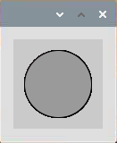
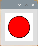
Each call of the draw() function takes the inverse of state and subsequently determines it. If the value is true, the LED is lit and the brush is filled with red; if not, the LED is turned off and the brush is filled with gray.
After completing the judgment, use the ellipse() function to draw a circle. It should be noted that width and height are system variables used to store the width and height of the display window.
There are two other points to note. When using GPIOs, you need to use the GPIO.pinMode() function to set the INPUT/OUTPUT state of the pin, and then use the GPIO.digitalWrite() function to assign a value (HIGH/LOW) to the pin .
Note
Please try to avoid using delay() in draw() because it will affect the display window refresh.