Note
Hello, welcome to the SunFounder Raspberry Pi & Arduino & ESP32 Enthusiasts Community on Facebook! Dive deeper into Raspberry Pi, Arduino, and ESP32 with fellow enthusiasts.
Why Join?
Expert Support: Solve post-sale issues and technical challenges with help from our community and team.
Learn & Share: Exchange tips and tutorials to enhance your skills.
Exclusive Previews: Get early access to new product announcements and sneak peeks.
Special Discounts: Enjoy exclusive discounts on our newest products.
Festive Promotions and Giveaways: Take part in giveaways and holiday promotions.
👉 Ready to explore and create with us? Click [here] and join today!
2.2.7 PIR
Introduction
In this project, we will make a device by using the human body infrared pyroelectric sensors. When someone gets closer to the LED, the LED will turn on automatically. If not, the light will turn off. This infrared motion sensor is a kind of sensor that can detect the infrared emitted by human and animals.
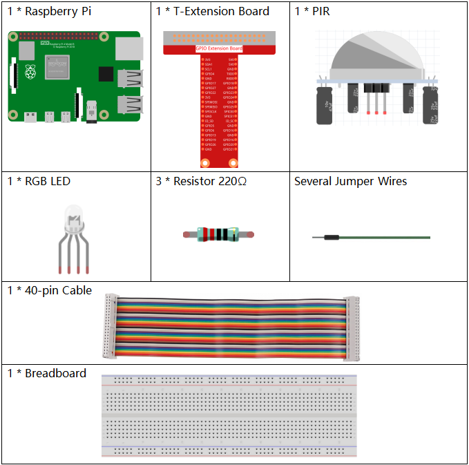
Required Components
In this project, we need the following components.
It’s definitely convenient to buy a whole kit, here’s the link:
Name |
ITEMS IN THIS KIT |
LINK |
|---|---|---|
Raphael Kit |
337 |
You can also buy them separately from the links below.
COMPONENT INTRODUCTION |
PURCHASE LINK |
|---|---|
- |
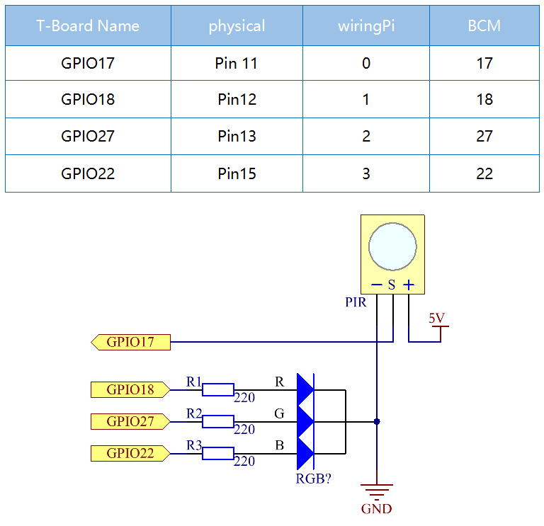
Schematic Diagram
Experimental Procedures
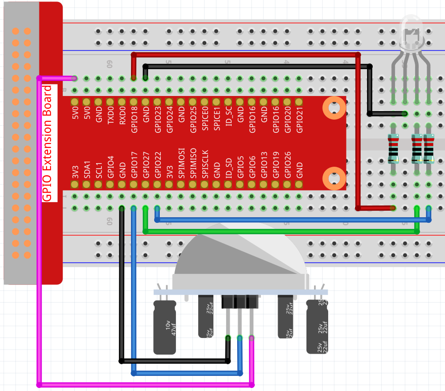
Step 1: Build the circuit.
Step 2: Go to the folder of the code.
cd ~/raphael-kit/nodejs/
Step 3: Run the code.
sudo node pir.js
After the code runs, PIR detects surroundings and let RGB LED glow yellow if it senses someone walking by. There are two potentiometers on the PIR module: one is to adjust sensitivity and the other is to adjust the detection distance. In order to make the PIR module work better, you need to try to adjust these two potentiometers.
Code
const Gpio = require('pigpio').Gpio;

const pirPin = new Gpio(17, {
    mode: Gpio.INPUT,
    pullUpDown: Gpio.PUD_DOWN,
    edge: Gpio.EITHER_EDGE
})    // the pir connect to pin17

const redPin = new Gpio(18, { mode: Gpio.OUTPUT, })
const greenPin = new Gpio(27, { mode: Gpio.OUTPUT, })
const bluePin = new Gpio(22, { mode: Gpio.OUTPUT, })
//'Red':18, 'Green':27, 'Blue':22

var p_R, p_G, p_B

// Set all led as pwm channel and frequece to 2KHz
p_R = redPin.pwmFrequency(2000)
p_G = greenPin.pwmFrequency(2000)
p_B = bluePin.pwmFrequency(2000)

// Set all begin with value 0
p_R.pwmWrite(0)
p_G.pwmWrite(0)
p_B.pwmWrite(0)

// Define a MAP function for mapping values.  Like from 0~255 to 0~100
function MAP(x, in_min, in_max, out_min, out_max) {
    return (x - in_min) * (out_max - out_min) / (in_max - in_min) + out_min
}

// Define a function to set up colors
function setColor(color) {
    // configures the three LEDs' luminance with the inputted color value .
    // Devide colors from 'color' veriable
    R_val = (color & 0xFF0000) >> 16
    G_val = (color & 0x00FF00) >> 8
    B_val = (color & 0x0000FF) >> 0
    // Map color value from 0~255 to 0~100
    R_val = MAP(R_val, 0, 255, 0, 100)
    G_val = MAP(G_val, 0, 255, 0, 100)
    B_val = MAP(B_val, 0, 255, 0, 100)

    //Assign the mapped duty cycle value to the corresponding PWM channel to change the luminance.
    p_R.pwmWrite(R_val)
    p_G.pwmWrite(G_val)
    p_B.pwmWrite(B_val)
    //print ("color_msg: R_val = %s, G_val = %s, B_val = %s"%(R_val, G_val, B_val))
}

pirPin.on('interrupt', (level) => {
    if (level) {
        setColor(0xFFFF00)
    }else{
        setColor(0x0000FF)
    }
});

process.on('SIGINT', function () {
    p_R.pwmWrite(0)
    p_G.pwmWrite(0)
    p_B.pwmWrite(0)
    process.exit();
})
Code Explanation
The code for this example is a combination of 2.1.1 Button and 1.1.2 RGB LED, no need to go into details.
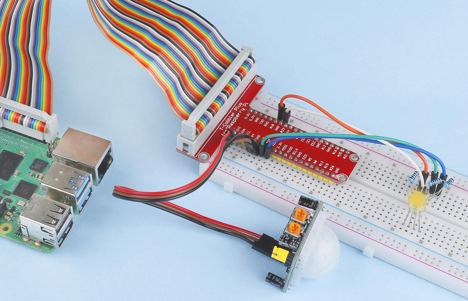
Phenomenon Picture